Eureka AIR delivers breakthrough ideas for toughest innovation challenges, trusted by R&D personnel around the world.

Method for estimating and suppressing direct current component of bridge inverter output voltage

A DC component and output voltage technology, applied in the direction of output power conversion devices, electrical components, etc., can solve the problems of system overcurrent, reduce system reliability, damage the power grid, etc., and achieve the effect of suppressing the DC component

Active Publication Date: 2018-11-23
厦门易实达新能源科技有限公司
View PDF6 Cites 4 Cited by
  • Summary
  • Abstract
  • Description
  • Claims
  • Application Information

AI Technical Summary

Problems solved by technology

In addition to causing additional losses, the inverter output voltage contains a DC component, which also has the following hazards: 1) If the inverter output DC component is too large, the output filter inductor will be saturated, making the inverter unable to work normally; 2) If the inverter output With an isolation transformer, it will cause the transformer to saturate and cause the system to overcurrent; 3) The DC component will cause serious asymmetry of the nonlinear load current and damage the electrical equipment; 4) For the inverter parallel system, the DC component will cause DC circulation, reducing the System reliability; 5) When the inverter is connected to the grid, the incoming current contains a DC component, which will damage the grid

Method used


Image

  • Method for estimating and suppressing direct current component of bridge inverter output voltage
  • Method for estimating and suppressing direct current component of bridge inverter output voltage
  • Method for estimating and suppressing direct current component of bridge inverter output voltage

Examples


Embodiment Construction

[0034] The technical solutions in the embodiments of the present invention will be described and discussed in detail below in conjunction with the drawings of the present invention. It should be understood that the specific embodiments described here are only used to explain the present invention, not to limit the present invention.

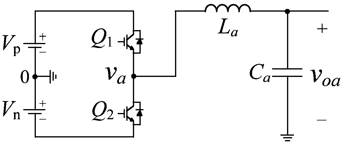
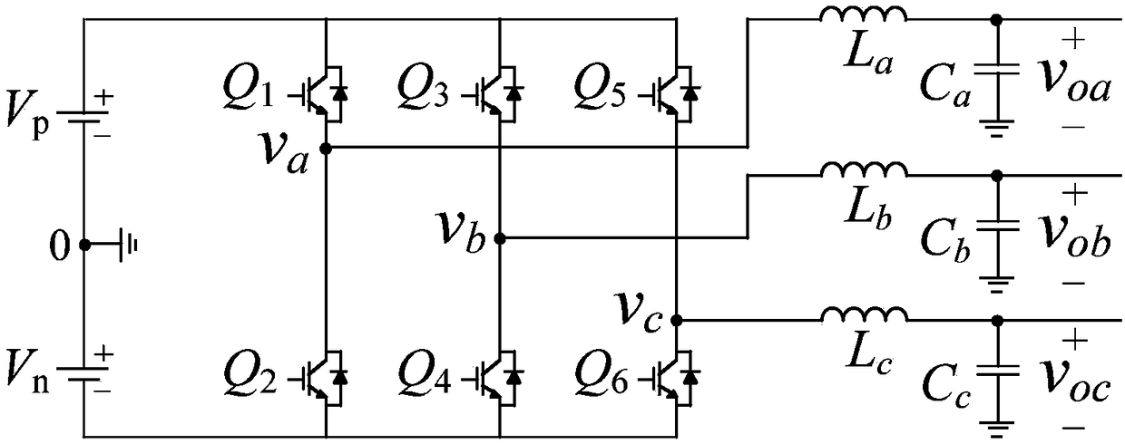
[0035] The present invention is suitable for digitally controlled single-phase half-bridge inverters and three-phase inverters; the circuit diagram of the single-phase half-bridge inverters can be found in figure 1 Shown, the circuit diagram of the three-phase inverter see figure 2 shown. The following takes a single-phase half-bridge inverter as an example to describe in detail.

[0036] see figure 1 As shown, the present invention is a method for estimating the DC component of the output voltage of a bridge inverter. The bridge inverter is a single-phase inverter; the single-phase inverter includes a DC bus voltage V p and V n , the first...


PUM


Abstract

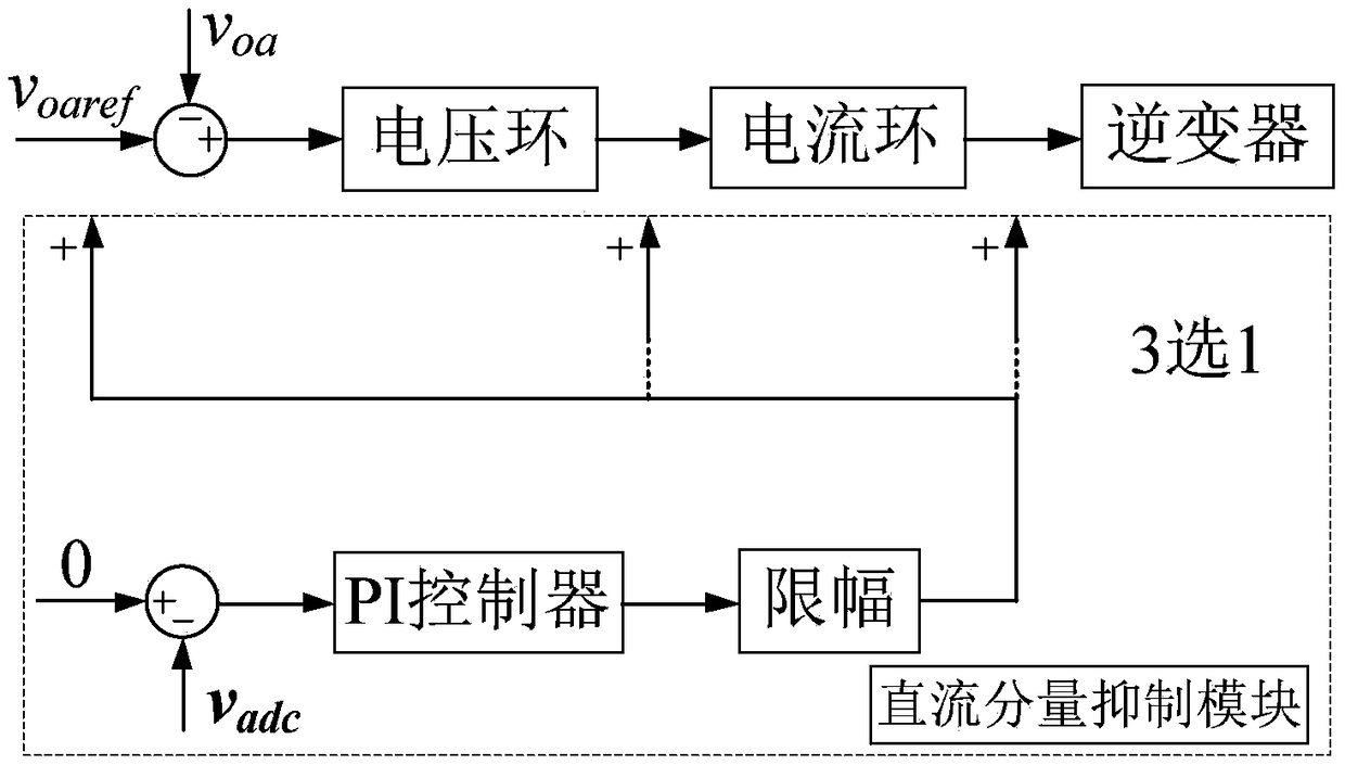
The invention relates to a method for estimating and suppressing a direct current component of a bridge inverter output voltage. Firstly, estimating a direct current component of an inverter bridge arm voltage and using it as an estimate value of the direct current component of an inverter output voltage; then adding a direct current component suppression module in a single-phase or a three-phasebridge inverter system; since the direct current component of the inverter bridge arm voltage is proportional to the direct current component of the inverter output voltage, the direct current component suppression module controls the direct current component of the inverter output voltage by controlling the direct current component of the inverter bridge arm voltage to be 0 or to close to 0, specifically, comparing the estimated direct current component of the inverter bridge arm voltage with 0 and compensating by a PI controller, superimposing the output value of the PI controller to a sinusoidal reference voltage, a voltage loop or a current loop output of the inverter after a certain limit processing. According to the method for estimating and suppressing direct current component of bridge inverter output voltage, the direct current component of the inverter bridge arm voltage and the direct current component of the inverter output voltage can be estimated, and the direct current component of the inverter output can be effectively suppressed.

Description

technical field [0001] The invention relates to the fields of electrical manufacturing technology and power supply equipment control technology, in particular to a method for estimating and suppressing a DC component of a bridge inverter output voltage. Background technique [0002] The limitation of traditional fossil energy and the problems of climate change and environmental pollution brought about by its widespread use make it difficult for the industrial and economic development model based on fossil energy to continue. Thanks to the promotion of the rapid development of renewable energy technology and information technology, the organizational structure, technical foundation and economic model of the world's energy industry are gradually changing. In this context, concepts such as distributed power generation, microgrid, smart grid, and energy internet have been proposed one after another, all with the key goal of promoting the flexible and efficient use of renewable e...

Claims


Application Information

Patent Timeline
Patent Type & Authority Applications(China)
IPC IPC(8): H02M1/12
CPCH02M1/12H02M1/0009H02M1/123
Inventor 林燎源
Owner 厦门易实达新能源科技有限公司
Why Eureka
Eureka Blog
Learn More