Multi-mode control method for voltage source type semi-active bridge DC-DC converter

A DC-DC, voltage source technology, applied in the direction of adjusting electrical variables, control/regulation systems, DC power input conversion to DC power output, etc., can solve the problems of low conversion efficiency, large circulation loss, etc., to achieve less heat generation, Reduced control dimension, high efficiency effect

Active Publication Date: 2018-11-23
BEIJING INSTITUTE OF TECHNOLOGYGY
View PDF2 Cites 6 Cited by
  • Summary
  • Abstract
  • Description
  • Claims
  • Application Information

AI Technical Summary

Problems solved by technology

[0006] In order to solve the problem of extremely low conversion efficiency caused by too much circulation loss under light load conditions of the voltage source semi-active bridge DC-DC converter using the traditional single phase shift control method, the voltage source semi-active bridge DC-DC converter disclosed in the present invention The technical problem to be solved by the multi-mode control method of the bridge DC-DC converter is: through full digital control, the converter can automatically switch seamlessly among the three control modes according to different load conditions, which can significantly improve the performance of the converter under light load. Conversion efficiency, so that the converter has a high conversion efficiency in the full load range, improving the power density of the converter

Method used


Image

  • Multi-mode control method for voltage source type semi-active bridge DC-DC converter
  • Multi-mode control method for voltage source type semi-active bridge DC-DC converter
  • Multi-mode control method for voltage source type semi-active bridge DC-DC converter

Examples


Embodiment 1

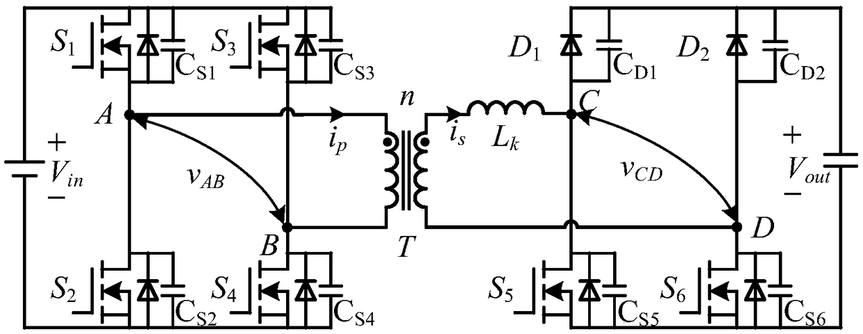
[0034] The multi-mode control method of the voltage source type semi-active bridge DC-DC converter disclosed in this embodiment, the mentioned embodiment is a voltage source type semi-active bridge DC-DC converter, the schematic diagram of the converter circuit structure is as follows figure 1 , mainly composed of the main circuit and the control circuit. The main circuit includes an input side, a transformer and an output side: the input side is a full-bridge circuit composed of four switching tubes, which is used to convert the input DC voltage into a high-frequency AC square wave voltage, so that the energy can be transferred from the primary side through the high-frequency transformer. Flow to the secondary side; the output side is a circuit composed of two switch tubes and two diodes (replacing the upper tube of each bridge arm in the full bridge circuit composed of four switch tubes with a diode), which is used to realize the output of the transformer Shaping of AC volta...


PUM


Abstract

The invention discloses a multi-mode control method for a voltage source type semi-active bridge DC-DC (Direct Current) converter, which belongs to the direction of high frequency switching power supply in the field of power electronics. The implementation method of the invention comprises the following steps that: in the case of heavy load, the converter operates in a traditional single phase shift control mode, the switching period is constant, and VAB high level time or low level time is constant; a output voltage Vout is adjusted to be stable by adjusting the phase shift between a input side voltage and a output side voltage; in the case of light load, the converter operates in a frequency modulation + PWM (Pulse Width Modulation) mode, and the VAB high level time or the low level timeis constant; VAB duty cycle is adjusted to be stable by adjusting a switching frequency, that is, a VAB period, that is, a fixed width frequency modulation mode; and in the case of extremely light load and no load, the converter operates in a constant frequency + PWM mode, that is, a fixed frequency width regulation mode. Three control modes can switch automatically and seamlessly based on load cases. According to the multi-mode control method for the voltage source type semi-active bridge DC-DC converter, conversion efficiency of the converter under the light load can be significantly improved, the converter has high conversion efficiency within a full load range, and power density of the converter is improved.

Description

technical field [0001] The invention relates to a multi-mode control method applied to a voltage source type semi-active bridge DC-DC converter, and belongs to the direction of high-frequency switching power supply in the field of power electronics. Background technique [0002] High-frequency isolated DC-DC converters are an important part of on-board battery charging for electric vehicles, and the input voltage for this application will only fluctuate within a small range due to the regulation of the AC-DC rectifier. However, the battery voltage will vary in a wide range during battery charging. These operating characteristics require that the used DC-DC converter can adapt to a wide output voltage range while achieving high conversion efficiency in the full load range. [0003] There are many circuit topologies suitable for battery charging, and the most widely used topology is the phase-shifted full-bridge DC-DC converter. However, due to the inherent defects of the tr...

Claims


Application Information

Patent Timeline
Patent Type & Authority Applications(China)
IPC IPC(8): H02M3/335
CPCH02M3/33515H02M3/33576
Inventor 沙德尚张健坤孙腾飞郭志强
Owner BEIJING INSTITUTE OF TECHNOLOGYGY
Why Eureka
Try Eureka