
A burr polishing device for cutting the inner wall of an automobile pipe fitting

A technology for pipe fittings and burrs is applied in the field of cutting and burr grinding devices for the inner wall of automobile pipe fittings, which can solve the problems of low grinding efficiency and poor practicability, and achieve the effects of improving grinding efficiency, novel design and reducing labor intensity

Inactive Publication Date: 2018-11-27
HEFEI LIANSEN YUTENG NEW MATERIAL TECH DEV CO LTD
View PDF1 Cites 8 Cited by
  • Summary
  • Abstract
  • Description
  • Claims
  • Application Information

AI Technical Summary

Problems solved by technology

[0003] Chinese patent (CN107971861A) discloses a device for grinding burrs on the inner wall of steel pipes, which includes multiple chutes and multiple slide plates. Although the device increases the grinding efficiency and quality to a certain extent, in each grinding process, The pipe fittings can only be polished once, the grinding efficiency is still relatively low, and the practicability is not strong

Method used


Image

  • A burr polishing device for cutting the inner wall of an automobile pipe fitting
  • A burr polishing device for cutting the inner wall of an automobile pipe fitting
  • A burr polishing device for cutting the inner wall of an automobile pipe fitting

Examples


Embodiment Construction

[0018] It should be noted that, in the case of no conflict, the embodiments of the present invention and the features in the embodiments can be combined with each other.

[0019] In describing the present invention, it should be understood that the terms "center", "longitudinal", "transverse", "upper", "lower", "front", "rear", "left", "right", " The orientations or positional relationships indicated by "vertical", "horizontal", "top", "bottom", "inner" and "outer" are based on the orientations or positional relationships shown in the drawings, and are only for the convenience of describing the present invention and Simplified descriptions, rather than indicating or implying that the device or element referred to must have a particular orientation, be constructed and operate in a particular orientation, and thus should not be construed as limiting the invention. In addition, the terms "first", "second", etc. are used for descriptive purposes only, and should not be understood ...


PUM


Abstract

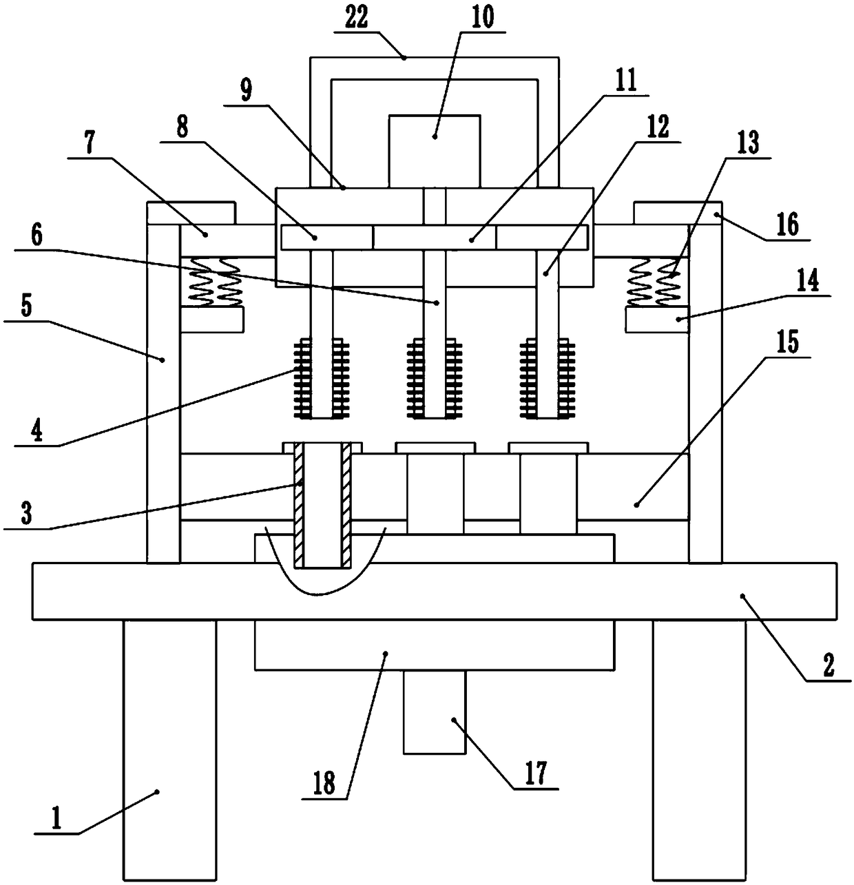
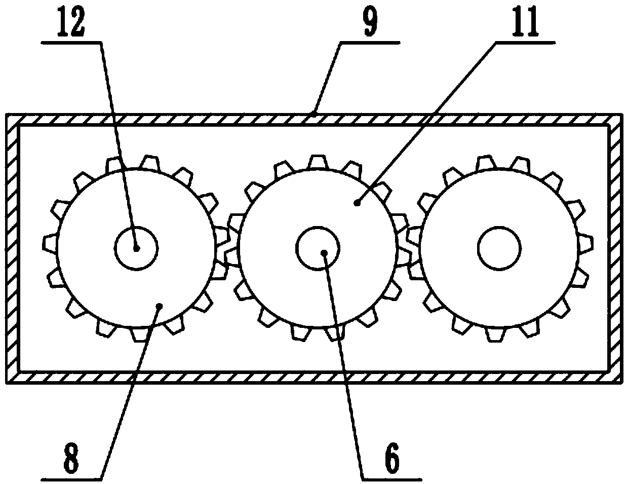
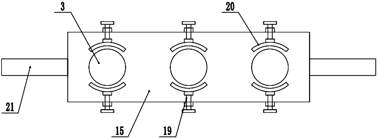
A burr polishing device for cutting inner wall of automobile pipe fitting including workbench, At both side of that lower end of the workbench are connecte support legs, A support frame is connecte onboth sides of that upper end of the work table, A cross beam is arranged in the middle of the support frame, A drive box is connected to the middle of the beam, A drive motor is connected to the upper end of the drive box, A low end of that drive motor is connected with a rotary shaft, A drive wheel is connected with the middle part of the rotary shaft, a driven wheel is engaged at both ends of the drive wheel, a polishing shaft is connected at the lower end of the driven wheel, a polishing head is connected at the bottom end of the polishing shaft, a fixing plate is connected between the lower ends of the support frame, a pipe groove is arranged at the middle part of the fixing plate, a clamping plate is connected at the upper end of the pipe groove, and fastening screws are connected atboth ends of the clamping plate. The invention not only reduces the labor intensity of the worker when polishing, but also improves the polishing efficiency of the automobile pipe fittings, meets thepolishing needs of a large number of automobile pipe fittings, and avoids setting a plurality of motors through the driven wheels, reduces the manufacturing cost, and is worth popularizing and using.

Description

technical field [0001] The invention relates to the technical field of processing equipment for automobile pipe fittings, in particular to a device for cutting burrs and grinding the inner wall of automobile pipe fittings. Background technique [0002] Pipe fittings are a general term for components that play the roles of connection, control, direction change, diversion, sealing, support, etc. in the piping system. Steel fittings are all pressure fittings. According to different processing techniques, it is divided into four categories, namely, butt-welding fittings (with and without welds), socket welding and threaded fittings, and flanged fittings. In the auto parts accessories, many accessories are pipe fittings structure, so we call the pipe fittings used in auto parts as auto pipe fittings. During the processing of automobile pipe fittings, we need to cut the pipe fittings in multiple sections, and then weld them into the desired multi-section bending shape of the aut...

Claims


Application Information

Patent Timeline
Patent Type & Authority Applications(China)
IPC IPC(8): B24B27/00B24B9/04B24B55/06B24B41/06B24B41/02B24B47/12
CPCB24B27/0076B24B9/04B24B27/0023B24B41/02B24B41/067B24B47/12B24B55/06
Inventor 程华风
Owner HEFEI LIANSEN YUTENG NEW MATERIAL TECH DEV CO LTD
Learn More