Plastic granulator

A plastic granule and granulator technology, applied in the field of plastic processing, can solve the problems of plastic granule sticking, affecting granulation quality, uneven particle size of plastic granules, etc., and achieve the effect of ensuring uniformity

Active Publication Date: 2018-11-27
惠州市启达环美科技有限公司
View PDF4 Cites 8 Cited by
  • Summary
  • Abstract
  • Description
  • Claims
  • Application Information

AI Technical Summary

Problems solved by technology

[0004] In order to overcome the current problem that the cooling effect of plastic granulation cannot be controlled, which affects the quality of granulation, and at the same time causes the problem of easy adhesion of plastic granules and the uneven p

Method used


Image

  • Plastic granulator
  • Plastic granulator
  • Plastic granulator

Examples


Embodiment

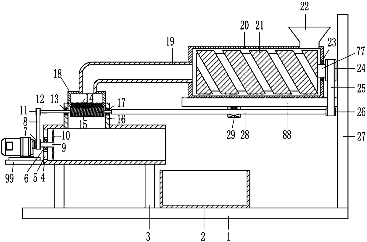
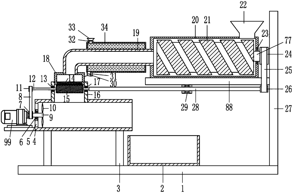
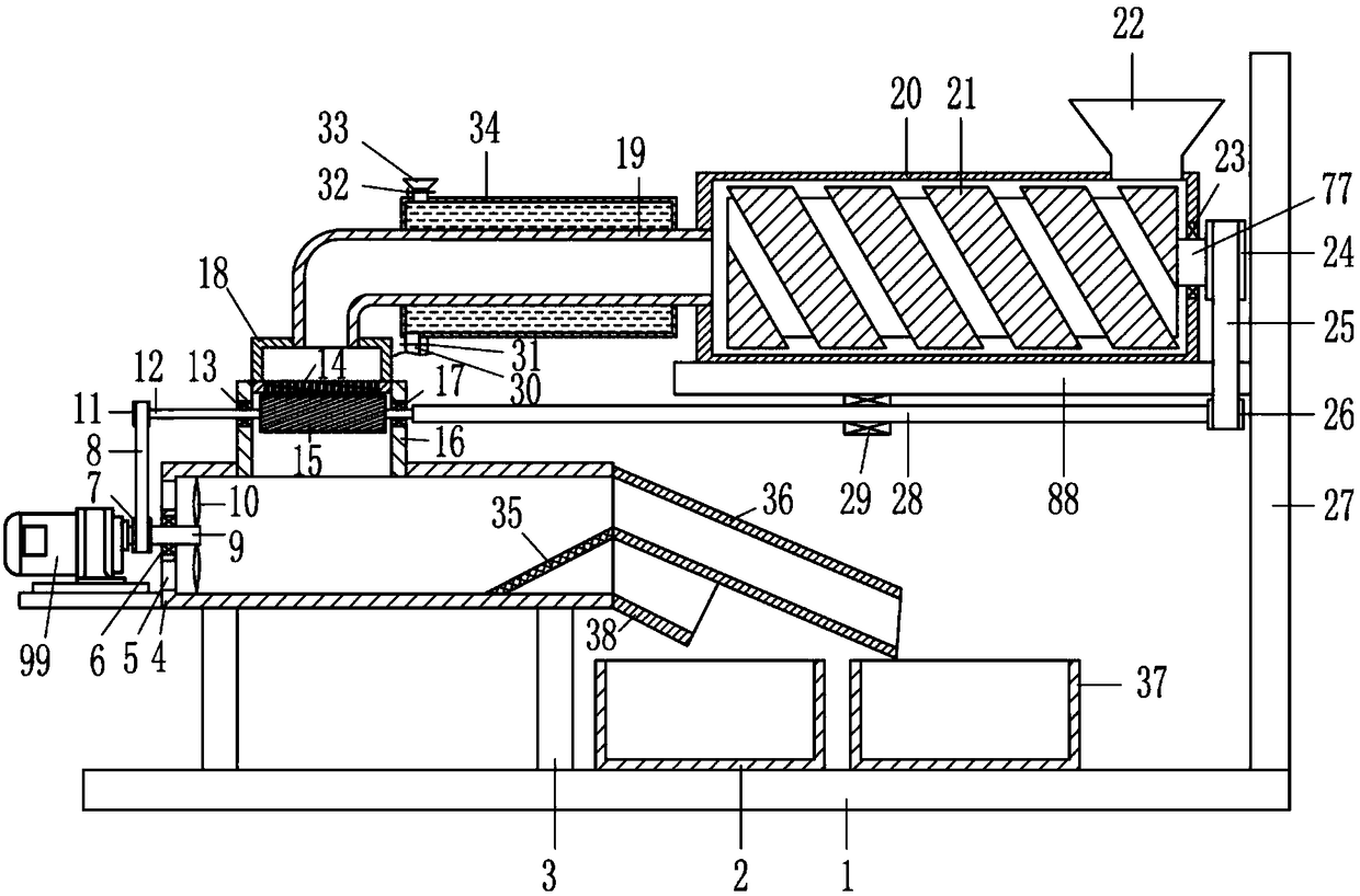
[0025] A plastic pellet granulator, such as Figure 1-5 As shown, it includes a first mounting plate 1, a first collection frame 2, a support seat 3, an air-drying frame 4, a first bearing seat 6, a first pulley 7, a first flat belt 8, a first rotating shaft 9, and a fan blade 10 , the second pulley 11, the second rotating shaft 12, the second bearing housing 13, the cutter roller 15, the pelletizing frame 16, the third bearing housing 17, the first extrusion frame 18, the cooling pipe 19, the second extrusion frame 20 , extrusion screw 21, lower hopper 22, fourth bearing block 23, third pulley 24, second flat belt 25, fourth pulley 26, second mounting plate 27, third rotating shaft 28, fifth bearing block 29, motor 99. The fourth rotating shaft 77 and the third mounting plate 88; the second mounting plate 27 is fixed to one side of the first mounting plate 1, and the air-drying frame 4 is fixed to the first mounting plate 1 through the support seat 3, away from the second mou...


PUM


Abstract

The invention relates to the field of plastic processing, in particular to a plastic granulator and aims to solve the problem of plastic particle adhesion and improve plastic particle size uniformity.The plastic granulator comprises a first mounting plate, a first collecting frame, supporting seats, an air drying frame, a first bearing seat, a first pulley, a first flat belt, a fourth rotating shaft, a third mounting plate and the like. A second mounting plate is fixedly connected to a lateral portion of the first mounting plate, and the air drying frame is fixedly connected to a lateral portion, away from the second mounting plate, of the first mounting plate. The first bearing seat is embedded to a lateral portion of the air drying frame. The plastic granulator has advantages that the plastic particles accumulated after granulation are less prone to adhesion, and the manufactured plastic particles can be screened and classified to guarantee plastic particle uniformity.

Description

technical field [0001] The invention relates to the field of plastic processing, in particular to a plastic particle granulator. Background technique [0002] The working principle of plastic granulation is: the plastic is plasticized and melted by the screw extruder, extruded into strips or strips through the die hole, cut into granules by the granulation equipment, and then subjected to secondary cooling to obtain Plastic granules of desired particle size. Extrusion forms can be divided into hot cut and cold cut. The so-called eager cutting refers to the method of pelletizing the material in a molten or semi-molten state after being extruded from the die hole of the machine head; while cold cutting refers to the method of pulling the material into strips after being extruded from the die hole of the machine head, and then enters the Method of pelletizing after cooling in a water tank [0003] At present, the cooling effect of plastic granulation cannot be controlled, wh...

Claims


Application Information

Patent Timeline
IPC IPC(8): B29B9/06B29B13/06B29B13/04B29B13/10
CPCB29B9/06B29B13/045B29B13/065B29B13/10
Inventor 冯睿杰
Owner 惠州市启达环美科技有限公司
Why Eureka
Try Eureka