Industrial furnace device

A technology for industrial furnaces and furnaces, which is applied in furnaces, crucible furnaces, furnace types, etc., can solve the problems of difficult control of the shell temperature of the furnace, affecting the practical life of the device, and the absence of a cooling system. Maintenance, prevention of affecting service life, and the effect of wide temperature control range

Inactive Publication Date: 2018-11-27
诸暨市亚瑟电子科技有限公司
View PDF0 Cites 0 Cited by
  • Summary
  • Abstract
  • Description
  • Claims
  • Application Information

AI Technical Summary

Problems solved by technology

[0002] With the development of science and technology and the progress of society, the country has been promoting the development of high technology. In the field of industrial furnace technology, there has always been a relatively difficult technical problem. The temperature of general industrial furnaces is limited. For some metals with relatively high melting points It is difficult to melt, which brings a big problem to the foundry and technology research industries. Traditional industrial furnaces need to be manually operated to pick and place metal. Because the temperature of molten metal after melting is extremely high, extraction is very dangerous, and general equipment does not There is a cooling system, and it is difficult to control the temperature of the shell of the kiln, which will affect the practical life of the device. This device effectively solves this problem

Method used


Image

  • Industrial furnace device
  • Industrial furnace device
  • Industrial furnace device

Examples


Embodiment Construction

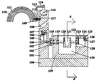
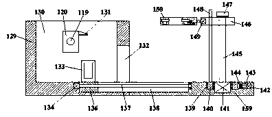
[0014] Such as figure 1 , figure 2 with image 3 As shown, an industrial furnace device of the present invention includes a base 100 and a supporting column 101 arranged on the top end of the base 100 and extending up and down. The top end of the base 100 is provided with the supporting column. The furnace barrel 129 at the right end of 101, the furnace barrel 129 is provided with an upwardly opening furnace cavity 130, the inner wall of the front end of the furnace barrel 129 is penetrated with a discharge port 132, and the front end of the furnace barrel 129 is provided with a The bottom plate 159 on the top of the base 100, the variable speed chamber 124 at the right end of the furnace chamber 130, the first rotating shaft 119 extending left and right is connected to the furnace chamber 130 for rotation, and the left end of the first rotating shaft 119 penetrates The left end of the furnace barrel 129 is provided with a voltage phase change plate 103 in the circumferential ...


PUM


Abstract

The invention discloses an industrial furnace device. The device comprises a base and a support column extending to the upper and lower portions arranged on the top end surface of the base, the top end of the base is provided with a furnace tube at the right end of the support column, a furnace chamber with an opening upward is arranged in the furnace tube, a discharge opening is formed in and penetrates through the inner wall of the front end of the furnace tube, a bottom plate located on the top of the base is arranged on the front end surface of the furnace tube, the right end of the furnace chamber is a shifting chamber, a first rotating shaft extending left and right is rotatably cooperatively connected in the furnace chamber, and the end of the left end of the first rotating shaft penetrates through the end of the left end surface of the furnace tube, and a voltage phase variable disk is circumferentially disposed; the device has a simple structure, convenient operation, a good smelting effect, a larger temperature control range and a higher temperature peak, and metals with a higher melting point are easily smelted.

Description

Technical field [0001] The invention relates to the technical field of industrial furnaces, in particular to an industrial furnace device. Background technique [0002] With the development of science and technology and the progress of society, the country has been promoting the development of high technology. In the field of industrial furnace technology, there has always been a relatively difficult technical problem. The temperature of general industrial furnaces is limited. For some metals with relatively high melting points It is difficult to melt, which brings a big problem to the casting and technical research industries. Traditional industrial furnaces require manual operation to pick and place the metal. Because the molten metal temperature is extremely high, the extraction is dangerous, and the general equipment is not The existence of a cooling system makes it difficult to control the temperature of the kiln's shell, which will affect the useful life of the device. This...

Claims


Application Information

Patent Timeline
Patent Type & Authority Applications(China)
IPC IPC(8): F27B14/02F27B14/06F27B14/08F27B14/16F27B14/20
CPCF27B14/02F27B14/061F27B14/08F27B14/0806F27B14/20F27B2014/0818F27B2014/0837
Inventor 何志辉
Owner 诸暨市亚瑟电子科技有限公司
Why Eureka
Try Eureka