Composite direct illumination type backlight module group

A backlight module and direct-type technology, applied in the field of direct-type backlight, can solve problems such as uneven failure, poor visual effect, unstable quality, etc., achieve high brightness parameter indicators, reduce production costs, and shorten the development cycle.

Active Publication Date: 2018-11-27
SHENZHEN SKYWORTH RGB ELECTRONICS CO LTD
View PDF10 Cites 4 Cited by
  • Summary
  • Abstract
  • Description
  • Claims
  • Application Information

AI Technical Summary

Problems solved by technology

Although the current direct-type backlight module can achieve a thinner shape, due to the limitations of cost, design space and lens technology, its shape is getting thinner and its edge is getting closer, that is, the light mixing distance and the shrinkage The smaller the corners, the smaller the area of ​​the bottom surface, resulting in fewer and fewer LEDs in the direct-type backlight module, and at the same time, the light from the LED to the corner becomes longer. To achieve high brightness indicators on the direct-type backlight module, Can only rely on high-cost optical film, such as prism film, DBEF, etc. On the one hand, the effect of the film on improving brightness is limited, far from reaching the grading standard; on the other hand, with the reduction of the light mixing distance and the number of LEDs , the distance between the LEDs increases, and the light mixing effect of the optical lens partially fails, resulting in uneven failure and serious vignetting. Therefore, the existing direct-lit backlight modules still have poor visual effects, low brightness, high cost, and poor quality. Insufficient stability requires a better direct-lit backlight design

Method used


Image

  • Composite direct illumination type backlight module group
  • Composite direct illumination type backlight module group
  • Composite direct illumination type backlight module group

Examples


Embodiment Construction

[0024] In order to make the objectives, technical solutions and advantages of the present invention clearer and clearer, the present invention will be further described in detail below with reference to the accompanying drawings and examples. It should be understood that the specific embodiments described herein are only used to explain the present invention, but not to limit the present invention.

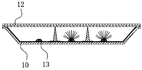
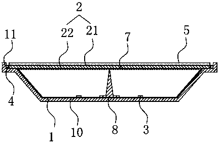
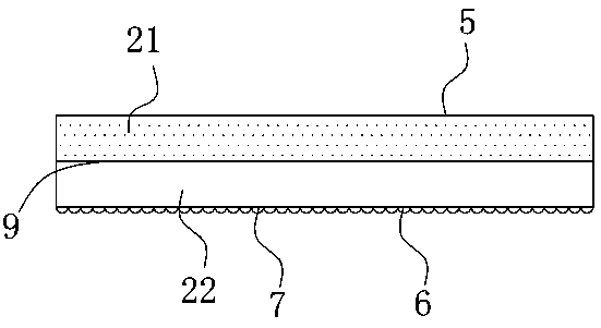
[0025] like figure 2 and image 3 As shown, a composite direct type backlight module includes a direct type backlight module and one or more sets of edge-type backlight module modules disposed on the side of the direct type backlight module.

[0026] The direct type backlight module includes a light guide diffuser plate 2 and a back plate 1 arranged under the light guide diffuser plate 2 . The direct-type LED light bar 3 and the reflective sheet 10 on the back panel 1 facing the light guide diffuser 2; the light guide diffuser 2 is made of polystyrene, and the light guide diffu...


PUM


Abstract

The invention discloses a composite direct illumination type backlight module group comprising a direct illumination type backlight module group body and one or more groups of lateral backlight modules arranged at the side of the direct illumination type backlight module group body. The direct illumination type backlight module group body consists of a light guiding diffusing plate, a back panel,direct illumination type LED light bars, and a reflection piece. The light guiding diffusing plate consists of a milky diffusion layer arranged at the half upper part of the light guiding diffusing plate and a transparent light guiding plate arranged at the half lower part of the light guiding diffusing plate. The back panel is arranged below the light guiding diffusing plate and is used for realizing mounting of the light guiding diffusing plate and the lateral backlight modules. The direct illumination type LED light bars are arranged on one side, facing the light guiding diffusing plate, ofthe back panel. Therefore, the ultra-thin direct illumination type product has the uniform picture and high brightness and the space is saved. Moreover, the process is simplified; the development cycle is shortened; and the production cost is lowered.

Description

technical field [0001] The invention relates to the field of direct type backlight, in particular to a compound type direct type backlight module. Background technique [0002] The current development trend of direct-lit backlight modules is ultra-thin and high-brightness. like figure 1 As shown, an existing ultra-thin direct type backlight module includes: a diffuser plate, a diaphragm 12, a reflection sheet 10, a lens 13, and the like. At present, although the direct type backlight module can achieve a thinner shape, due to the limitations of cost, design space and lens technology, its shape is getting thinner and the edge is getting closer and closer, that is, the light mixing distance and the receiving The smaller the corners, the smaller the area of ​​the bottom surface, resulting in fewer and fewer LEDs in the direct-lit backlight module, and at the same time, the light from the LEDs to the corners becomes longer. To achieve high brightness indicators on the direct-l...

Claims


Application Information

Patent Timeline
Patent Type & Authority Applications(China)
IPC IPC(8): G02B6/00
CPCG02B6/004G02B6/0073G02B6/0091
Inventor 刘欣尤君平李坚
Owner SHENZHEN SKYWORTH RGB ELECTRONICS CO LTD
Why Eureka
Try Eureka