Remote control system of household electrical appliances

A technology for remote control systems and household appliances, applied in electrical program control, general control systems, control/regulation systems, etc., can solve the problems of poor real-time performance, difficult application, and high equipment costs

Inactive Publication Date: 2018-11-27
FUZHOU ZHUNDIAN INFORMATION TECH CO LTD
View PDF0 Cites 1 Cited by
  • Summary
  • Abstract
  • Description
  • Claims
  • Application Information

AI Technical Summary

Problems solved by technology

[0004] The detection of TW ACS signals is mainly based on time-domain difference technology. Most of these methods have complex data processing, poor real-time performance, and high equipment costs. Determine whether the signal bit is "1" or "0". Due to the rigor of the calculation, the interference signal will seriously affect the judgment result of the detected signal, so the original method is difficult to apply in our country

Method used


Image

  • Remote control system of household electrical appliances
  • Remote control system of household electrical appliances

Examples


Embodiment Construction

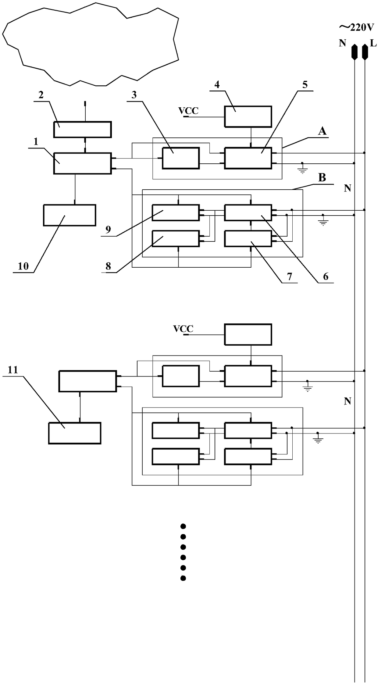
[0052] The block diagram of the circuit structure of a remote control system for home appliances is as follows: figure 2 shown. Including centralized controller and multiple electrical controllers. The centralized controller is composed of a signal sending terminal A, a signal receiving terminal B, a network interface module 2 , a keyboard display module 10 and a microcontroller module 1 . The electrical appliance controller is composed of a signal sending terminal A, a signal receiving terminal B, an electronic switch 11 and a microcontroller module 1 . The centralized controller communicates with the electrical appliance controller through the power line. The main station is the computer management system located on the top layer, which is composed of routers and computers.

[0053] The hardware structures of the power line communication signal sending end A, signal receiving end B, microcontroller module 1 and power supply module 4 in the centralized controller and the ...


PUM


Abstract

The invention relates to a remote control system of household electrical appliances. Electrical appliance controllers control start-up and shut-down of the electrical appliances of air conditioner equipment and the like through electronic switches. A small telephone program-controlled exchanger is installed in a house, one of extension numbers is used for remote control, the exchanger receives number signals of instruction codes and transfers the number signals of the instruction codes to an integrated controller, and after decoding is conducted by the integrated controller, corresponding operation is executed. The integrated controller has access to the Internet through a network interface module so that a computer and hand-held mobile equipment can be used for visiting a remote computermanagement system.

Description

(1) Technical field: [0001] The invention relates to a remote control system for household electrical appliances, which includes a centralized controller and various electrical appliance controllers, and uses a power line communication method to send a wide pulse signal to a specific point in the grid cycle voltage crossing 0 area to generate a sudden change current, so that the grid cycle carries information. The centralized controller receives the data collected by each electrical controller, and connects to the Internet through the network interface module integrated with the TCP / IP hardware protocol stack, so that computers and handheld mobile devices can be used to access the remote computer management system. (two) background technology: [0002] Current power line communication mainly refers to power line carrier communication and two-way power frequency communication. Power line carrier communication PLC uses the existing power line to transmit signals through carrie...

Claims


Application Information

Patent Timeline
Patent Type & Authority Applications(China)
IPC IPC(8): G05B19/418G05B15/02
CPCG05B15/02G05B19/4186G05B2219/2642
Inventor 张金木
Owner FUZHOU ZHUNDIAN INFORMATION TECH CO LTD
Why Eureka
Try Eureka