Inwardly double inlet-type multistage separation type dust collector

A multi-stage separation and vacuum cleaner technology, applied in the direction of vacuum cleaners, suction filters, exhaust diffusion devices, etc., can solve the problem of poor dust separation effect, and achieve the effect of strengthening centrifugal separation effect, strengthening airflow, and relatively less conflict.

Active Publication Date: 2018-11-30
NINGBO HAIJI ELECTRIC APPLIANCE
View PDF4 Cites 0 Cited by
  • Summary
  • Abstract
  • Description
  • Claims
  • Application Information

AI Technical Summary

Problems solved by technology

Among them, the cyclone separation vacuum cleaner mainly uses the principle of centrifugal separation to strengthen the separation effect of dust (dust) and has been widely cited. However, the current cyclone separation vacuum cleaner, due to the attenuation of the airflow process, Often cannot fully achieve the effect of centrifugal separation, which will easily lead to poor actual dust separation effect

Method used


Image

  • Inwardly double inlet-type multistage separation type dust collector
  • Inwardly double inlet-type multistage separation type dust collector
  • Inwardly double inlet-type multistage separation type dust collector

Examples


Embodiment 1

[0031] Embodiment 1: as figure 1 , figure 2 , image 3 , Figure 4 , Figure 5 as shown in

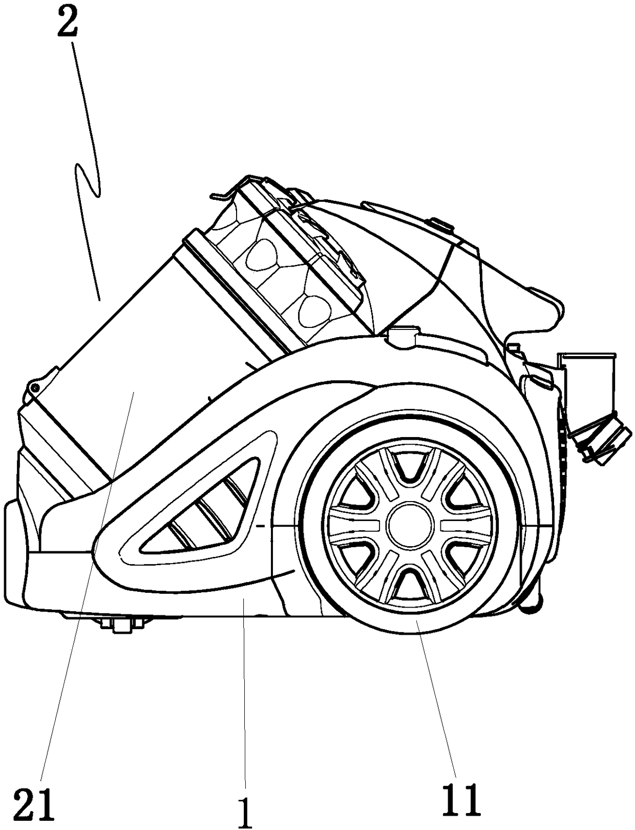
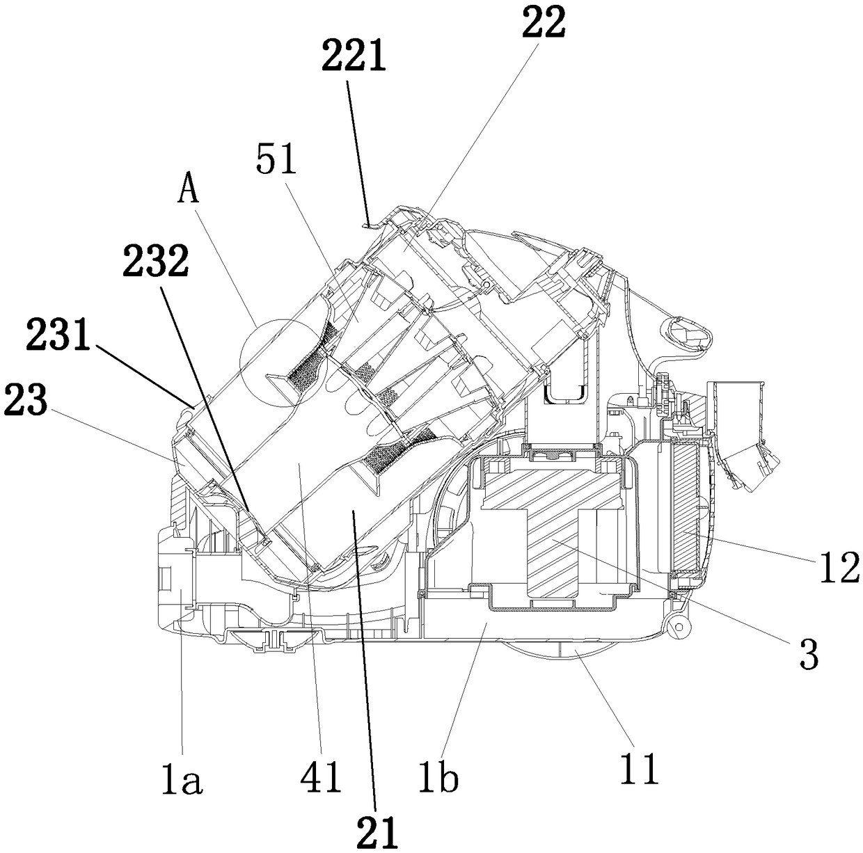
[0032] An inner double-inlet multi-stage separation vacuum cleaner, comprising

[0033] Case 1, dust cup 2 and dust collection motor 3; the dust cup includes a cup body 21, a cup cover 22 and a bottom cover 23, the cup cover is clamped with the cup body, and the bottom cover is clamped with the cup body;

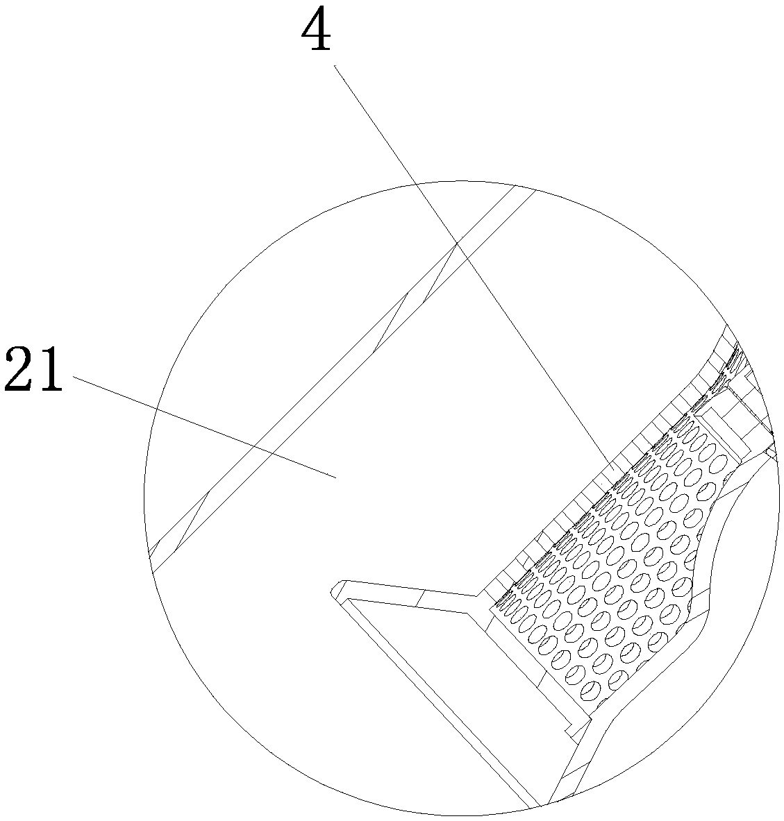
[0034] The dust cup is provided with a first air inlet and a first air outlet, and a filter cartridge 4 and a secondary separator are arranged in the cup body, the secondary separator separates the cup cover from the cup body, and the secondary separator includes multiple A cyclone separation cone 51, the diameter of the lower port of the cyclone separation cone is smaller than the diameter of the upper port, the side wall of the cyclone separation cone is provided with two tangential air inlet pipes inside the cup cover, and the lower end of the cyclone separation cone communi...

Embodiment 2

[0045] Embodiment 2: based on embodiment 1, such as Figure 6 as shown,

[0046] It also includes a mop 6, an elastic bellows and an operating hard tube 7. The mop is provided with a mop chamber 6a, and the mop is provided with a bottom suction port 6b connected with the mop chamber and an upper suction port connected with the mop chamber. Air outlet pipe 61, the lower end of the operating hard pipe is snapped and communicated with the upper air outlet pipe, the upper end of the operating hard pipe is snapped and communicated with one end of the elastic bellows, and the other end of the elastic bellows is snapped and communicated with the main suction port. A ground mop front wheel and two coaxially arranged ground mop rear wheels 62 are provided on the top. When using a vacuum mop, you can hold the operating hard tube to drive the vacuum mop to move on the ground, thereby vacuuming everywhere.

Embodiment 3

[0047] Embodiment 3: based on embodiment 2, such as Figure 7 , Figure 8 , Figure 9 , Figure 10 as shown,

[0048] The lower part of the front end of the dust-absorbing floor mop is provided with a front suction hole 6c, and the front suction hole is provided with a horizontal column 63 that is slidingly and sealingly matched with the front suction hole. The horizontal column includes an inner guide hemispherical head 631, a column body 632 and an outer Guide hemispherical head 633, the mop cavity is provided with a sealing plate 64 for sealing the bottom suction port, the side of the sealing plate adjacent to the front suction hole is hinged with the inner bottom surface of the vacuum mop, and the inner guiding hemispherical head is provided with a sealing plate for pressing down The pressure plate 65, there is a margin gap between the pressure plate and the sealing plate, a connecting rope 66, a rope spring 67, a slider 681 connected with the pressure plate and a limit...


PUM


Abstract

The invention discloses an inwardly double inlet-type multistage separation type dust collector. The dust collector comprises a housing, a dust cup and a dust collection motor. The dust cup comprisesa cup body, a cup cover and a bottom cover. A first air inlet and a first air outlet are arranged in the dust cup. The inside of the cup body is equipped with a filter cylinder and a second-stage separator. The second-stage separator separates the cup cover from the cup body. The second-stage separator comprises multiple cyclone separation cones. Lower end openings of the cyclone separation conesare less than the opening diameter of the upper end. The side wall of each cyclone separation cone is equipped with two tangential air supply pipes located in the interior of the cup cover. The lowerend of each cyclone separation cone communicates with the interior of the filter cylinder. The upper end of each cyclone separation cone communicates with the interior of the cup cover. The housing isequipped with a primary suction opening and a main discharge opening. The inwardly double inlet-type multistage separation type dust collector has the following beneficial effects: air flows can be dispersed in order to increase relative flow speed of each dispersion air flow; additionally, by increasing relative air inlet amount, centrifugal separation effect is enhanced; the final separation effect of dust is improved; and the dust collection capability is strong.

Description

technical field [0001] The invention belongs to the technical field of vacuum cleaners, in particular to an inner double-inlet multi-stage separation vacuum cleaner. Background technique [0002] The vacuum cleaner is a common electrical appliance. The working principle of the vacuum cleaner is: use the vacuum motor to generate negative air pressure in the sealed casing to absorb dust. There are many types of vacuum cleaners, which can be divided into vertical, horizontal and portable according to the structure, and can be divided into cyclone separation type, dust bag separation type, electrostatic precipitator type, etc. according to the separation method. Among them, the cyclone separation vacuum cleaner mainly uses the principle of centrifugal separation to strengthen the separation effect of dust (dust) and has been widely cited. However, the current cyclone separation vacuum cleaner, due to the attenuation of the airflow process, Often the effect of centrifugal separa...

Claims


Application Information

Patent Timeline
Patent Type & Authority Applications(China)
IPC IPC(8): A47L5/16A47L9/10A47L9/00A47L9/16
CPCA47L5/16A47L9/00A47L9/0081A47L9/102A47L9/1683
Inventor 周荣郑良宝
Owner NINGBO HAIJI ELECTRIC APPLIANCE
Why Eureka
Try Eureka