Jet vacuum-pumping rapid water diversion device

A jet device and vacuum pumping technology, applied in the mechanical field, can solve the problems of affecting the sealing effect, heavy bottom valve, failure of the bottom valve, etc., and achieve the effect of light weight and small volume

Pending Publication Date: 2018-09-11
AMOS FLUID TECH CO LTD
View PDF0 Cites 0 Cited by
  • Summary
  • Abstract
  • Description
  • Claims
  • Application Information

AI Technical Summary

Problems solved by technology

Although the pump is equipped with a bottom valve, the bottom valve has natural defects, which are mainly manifested in: 1. The bottom valve is heavy and installed under the liquid, which is not easy to install, monitor, maintain and repair; 2. The bottom valve is immersed in water for a long time. In the liquid, it is easy to cause corrosion, which will affect the sealing effect. If it is serious, it will not work when it absorbs water for the second time; 3. The solid particles generated in the production and process will enter the circulating liquid, and the accumulation and adhesion of solid particles in the bottom valve Attachment can prevent the bottom valve from being fully sealed, and the bottom valve will fail immediately; 4. Since the bottom valve is installed at the water inlet, the bottom valve itself will affect the water inlet area of ​​the pump and cause insufficient water supply

Method used


Image

  • Jet vacuum-pumping rapid water diversion device
  • Jet vacuum-pumping rapid water diversion device
  • Jet vacuum-pumping rapid water diversion device

Examples


Embodiment 1

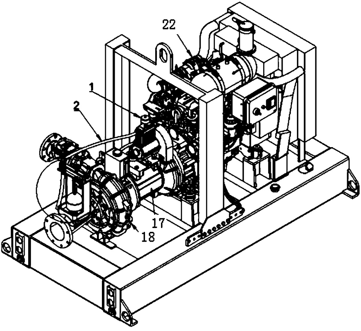
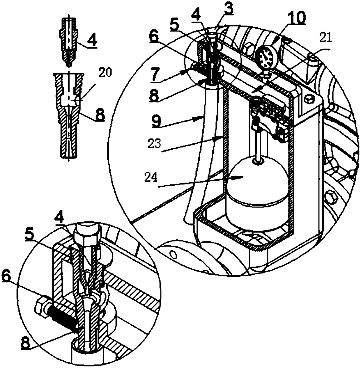
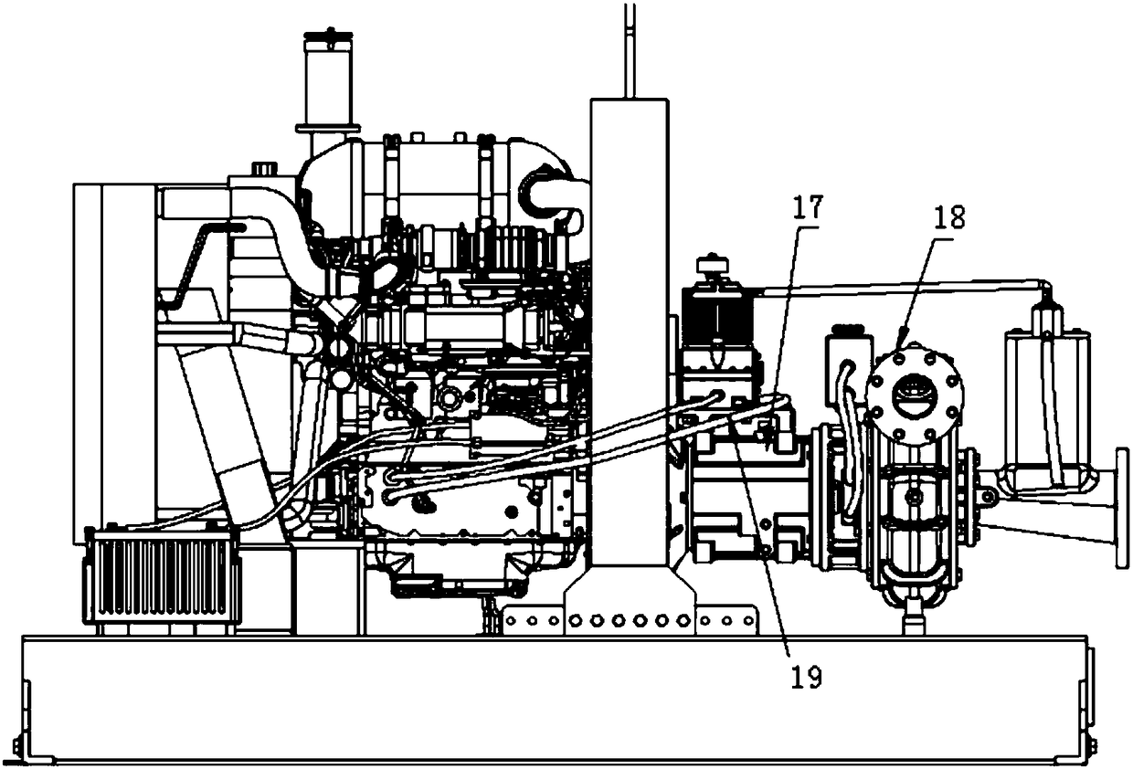
[0020] Embodiment 1: Referring to the accompanying drawings, the supporting air compressor 1 is directly installed on the suspension 17 of the centrifugal pump 18, and is connected to the shaft drive of the centrifugal pump through a belt. The air compressor 1 can also be installed on the diesel engine 16, and the intake pipe 2 It is a high-temperature-resistant and high-pressure-resistant air pipe, which is used to connect the exhaust port of the air compressor 1 and the jet device. The 90° elbow 3 is used for the conversion connection between the intake pipe 2 and the throat pipe 4 of the jet pump device. The bolt 5 withstands the jet The jet tube 6 of the device is fixed in the suction chamber 23 of the centrifugal pump 12, the inlet of the jet tube 6 communicates with the pump chamber of the centrifugal pump, and the jet tube 6 passes through the suction chamber and is sealed by O-rings 5 ​​and 6. The float switch 24 in the suction chamber is used to automatically close the...

Embodiment 2

[0026] Embodiment 2: The supporting air compressor 1 is directly installed on the suspension 17 of the centrifugal pump 18, and is connected to the pump shaft drive of the centrifugal pump by a belt. The air compressor 1 can also be installed on the diesel engine 22. The high-pressure resistant air pipe is used to connect the exhaust port of the air compressor 1 and the throat pipe 15 of the jet device, the throat pipe 15 is connected with the injection pipe 16 by threads, and the inlet 20 of the injection pipe 16 is connected to the 90° elbow 14, The three-way pipe 13, the ball valve 11 and the outer wire directly 12 until the inlet pipe of the centrifugal pump communicates with the pump chamber, the vacuum pressure gauge 10 is connected to the other interface of the three-way 13, and the exhaust hose 9 is connected to the end of the jet pipe 16 for Diversion and noise reduction of exhaust gas.

[0027] The principle of embodiment 2, such as Figure 4 , 5 , 6;

[0028] The...


PUM


Abstract

The invention discloses a jet vacuum-pumping rapid water diversion device comprising a diesel engine, an air compressor, a jet device, connecting pipes and other pipes, a ball valve, a floating ball switch and a vacuum pressure gauge. The water diversion device is characterized in that the jet device comprises a jet pipe and a Venturi pipe, and the air compressor is installed on the diesel engineon a supporting seat or a supporting centrifugal pump; an exhaust port of the air compressor is connected to an air inlet pipe of which the end is connected to the Venturi pipe, and the Venturi pipe is in screw joint with the jet pipe of which the side wall is provided with a jet pipe inlet; the jet pipe inlet communicates with a chamber of the supporting centrifugal pump, and the bottom of the Venturi pipe is connected to an exhaust hose; and the air compressor is driven by the diesel engine. According to the water diversion device, the time for the centrifugal pump ready to start can be shortened greatly, and the secondary self-priming working efficiency is improved; the production loss caused by long-time shutdown is decreased, and the labor cost is reduced; especially, the emergency rescue work can be quickly started, and the disaster loss is reduced; and meanwhile, artificial potential safety hazards can be avoided effectively, and the labor intensity is reduced.

Description

technical field [0001] The invention relates to the field of mechanical technology, in particular to a jet vacuum quick water diversion device matched with various dry-installed centrifugal pump equipment. Background technique [0002] In the field of general-purpose pumps, general non-submersible centrifugal pumps, except self-priming pumps with their own self-priming function and ordinary centrifugal pumps relying on positive pressure water intake, most dry-installed centrifugal pumps need to be configured Bottom valve, before starting for the first time, the pump needs to be filled with water to start. Although the pump is equipped with a bottom valve, the bottom valve has natural defects, which are mainly manifested in: 1. The bottom valve is heavy and installed under the liquid, which is not easy to install, monitor, maintain and repair; 2. The bottom valve is immersed in water for a long time. In the liquid, it is easy to cause corrosion, which will affect the sealing...

Claims


Application Information

Patent Timeline
IPC IPC(8): F04D9/06
CPCF04D9/006F04D9/065
Inventor 梅海清
Owner AMOS FLUID TECH CO LTD
Why Eureka
Try Eureka