Impurity collecting and discharging device

A discharge device and impurity technology, applied to the separation of dispersed particles, chemical instruments and methods, separation methods, etc., can solve the problems of poor impurity discharge, low cost, and inconvenient installation of the separation device

Inactive Publication Date: 2018-11-30
石家庄欧亚惠通滤清器有限公司
View PDF0 Cites 1 Cited by
  • Summary
  • Abstract
  • Description
  • Claims
  • Application Information

AI Technical Summary

Problems solved by technology

[0006] In view of this, the object of the present invention is to overcome the above-mentioned shortcomings of the prior art, and provide a fluid impurity separation device with high impurity separation efficiency and low cost, which can greatly improve the separation efficiency of the separation device, and the dust removal rate is as high as 98.4%. above; at the same time, on the premise of ensuring high-efficiency separation, the problems of po

Method used


Image

  • Impurity collecting and discharging device
  • Impurity collecting and discharging device
  • Impurity collecting and discharging device

Examples


Embodiment 1

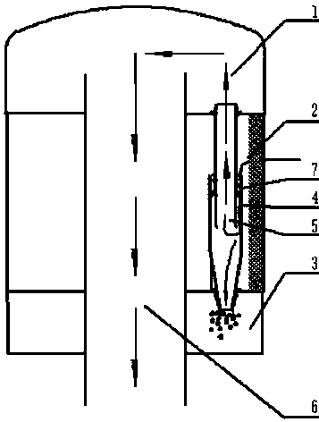
[0066] Embodiment 1: A kind of fluid impurity separation device, see figure 1 and figure 2 , including: including the first cavity 1, the second cavity 2, the third cavity 3, the fourth cavity 4, the fifth cavity 5, the sixth cavity 6 and the swirl tube 10, wherein the first cavity 1. The second cavity 2 and the third cavity 3 are arranged sequentially from top to bottom. The second cavity 2 communicates with the outside. The external fluid first enters the second cavity 2 and then flows into the fourth cavity 4. The fourth cavity The upper part of the body 4 communicates with the second cavity 2, the lower part of the fourth cavity 4 communicates with the third cavity 3, the fifth cavity 5 is located inside the fourth cavity 4 and communicates with the inside of the fourth cavity 4, and the fifth cavity The upper part of the body 5 communicates with the first cavity 1, the sixth cavity 6 is located at the central axis of the separation device, the upper part of the sixth ca...

Embodiment 2

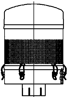
[0090] Embodiment 2: see attached Figure 1-5 , The modular air primary filter dust collector includes a cap-shaped top cover, a modular dust collector housing, a swirl tube air filter device, an air intake grille, an air outlet pipe, a dust collection chamber and an automatic ash discharge device, a cap-shaped top cover, The modular dust collector shell and the dust collection chamber are composed of three parts sealed and connected. In order to facilitate the disassembly of internal components, the hat-shaped top cover, the modular dust collector housing and the dust collection chamber can be detachably connected together through threaded structures, snap-fit ​​structures, etc.

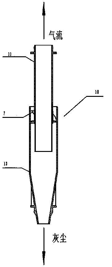
[0091] The shell of the dust collector is cylindrical, with a height of 409.5cm and a diameter of the cylindrical part of 307cm. The swirl tube 10 is arranged in the shell and is located below the air intake grille. The swirl tube 10 is arranged in the vertical direction. Two circles of swirl tubes...


PUM


Abstract

The present invention discloses an impurity collecting and discharging device which is used in a cyclone pipe type fluid pre-filter. A middle part of a fluid pre-filter shell body is vertically provided with a fluid discharge pipe along an axis direction; a cyclone pipe is arranged between the outer wall of the fluid pre-filter shell body and a fluid discharge pipe; the lower part of the cyclone pipe is provided with an impurity collecting device; an inner annular opening of the impurity collecting device communicates with the fluid discharge pipe; an impurity collecting box with an opening upward; a plurality of impurity-receiving chambers are divided by setting a plurality of vertical partition plates in the impurity collecting box; the impurity collecting box is made from a transparentmaterial; the lower part of the impurity collecting box is provided with an impurity automatic discharging device; the impurity automatic discharging device comprises a plurality of impurity discharging ports and impurity guiding grooves; the number of the impurity discharging ports is the same as the number of the impurity-receiving chambers; and besides, the arranging position of each impurity discharging port corresponds to the position of each impurity-receiving chamber. The provided impurity collecting and discharging device can avoid problems that impurities of separating devices are notdischarged smoothly and installation is inconvenient under a premise of ensuring high-efficiency separation.

Description

[0001] technical field [0002] The invention relates to a fluid filtration and purification system, in particular to an efficient fluid impurity separation device, a swirl tube type fluid prefilter, an impurity collection device and an impurity collection and discharge device. Background technique [0003] The fluid impurity separation device widely used in construction machinery and agricultural machinery equipment in my country, its separation efficiency is restricted by technical conditions, the separation effect is not good, and the function is single. At present, this kind of fluid impurity separation device is roughly divided into three categories: basin prefilter, swirl tube prefilter and automatic dust removal prefilter. The corresponding filtration efficiencies are: basin prefilter ≥ 70%, rotary Flow tube pre-filter ≥ 80%, automatic dust-exhaust pre-filter ≥ 80%, it can be said that the separation effect of the current separation device is not good for impuritie...

Claims


Application Information

Patent Timeline
IPC IPC(8): B01D45/16B01D45/18
CPCB01D45/16B01D45/18
Inventor 陈爱冬冯金凤冯秀培
Owner 石家庄欧亚惠通滤清器有限公司
Why Eureka
Try Eureka