Using method for numerical control dual-flying-saw cold slitting machine

A flying saw and cutting machine technology, applied in the direction of metal sawing equipment, sawing machine, metal processing equipment, etc., can solve the problems that the production efficiency of the flying saw machine has not been improved, the production efficiency needs to be improved, and the NC programming is complicated, so as to reduce the failure Hidden dangers, improved production efficiency, and easy NC programming

Inactive Publication Date: 2018-11-30
晋江市伟业城金属制品有限公司
View PDF7 Cites 2 Cited by
  • Summary
  • Abstract
  • Description
  • Claims
  • Application Information

AI Technical Summary

Problems solved by technology

[0004] As shown in the invention patent application with the application publication number CN103386506A, an adjustable steel pipe flying saw machine includes a worktable, a walking trolley that can move horizontally on the workbench, and a cutting device installed on the walking trolley. The cutting device It includes a driving motor, a support, a swing arm, a transmission shaft, and a flying saw blade. The driving motor is connected to the transmission shaft through a transmission belt, and the transmission shaft is connected to the flying saw blade. The transmission shaft is installed on the upper part of the swing arm, and the lower part of the swing arm passes through The rotating shaft is installed on the support, the bottom of the swing arm is connected with the piston rod of the oil cylinder, the middle part of the swing arm is connected with a small rotating shaft, and the outside of the small rotating shaft is connected with a tensioning wheel, and the tensioning wheel contacts the transmission belt. The lead screw of the walking trolley, the inside of the walking trolley is provided with an internal thread that meshes with the lead screw, and one end of the lead screw is connected to the motor. This kind of adjustable steel pipe flying saw machine can realize automatic cutting, but each cutting can only produce A steel pipe, the production efficiency needs to be improved
[0005] For this reason, the invention patent with the authorized announcement number CN205309443U provides a double-vehicle type fixed-length flying saw machine, including: two sets of fixed-length cutting devices, and the two sets of fixed-length cutting devices are symmetrically arranged on the cut workpiece The left and right sides of the left and right sides; the cut-to-length device, including: a saw car, a machine base, a workpiece clamping mechanism set on the saw car, a cutting feed mechanism set on the saw car and a cutting machine set at the feed end of the cutting feed mechanism. Mechanism; the upper end of the machine base is provided with a walking table for the saw car to walk, and a running mechanism for driving the saw car to walk on the walking table is provided between the saw car and the walking table; the workpiece clamping mechanism is a cantilever clamping mechanism; the above technology is adopted The present invention of scheme has two flying saws to cooperate with work cutting, can improve production efficiency to a certain extent, but still has the following problems: as described in the description, two sets of cut-to-length cutting devices are serially cut off workpieces sequentially. One set of cut-to-length device saw car accelerates synchronously with the unit, clamps the workpiece, and the saw blade cuts the workpiece. At the same time, the other set of cut-to-length device is on standby at the initial origin, and the two sets of cut-to-length devices cut off the workpiece alternately, so at the same time There is only one set of cutting-to-length device for cutting work, and the other set is in standby mode, which does not give full play to the functions of the two sets of cutting devices. Compared with the traditional flying saw machine, the production efficiency is actually not doubled, and the two sets of cutting-to-length The sequential linkage control action of the device relies on more control units, the potential for failure is higher, and the NC programming is more complicated, so there is still a large room for technical improvement

Method used


Image

  • Using method for numerical control dual-flying-saw cold slitting machine
  • Using method for numerical control dual-flying-saw cold slitting machine
  • Using method for numerical control dual-flying-saw cold slitting machine

Examples


Embodiment Construction

[0035] The present invention will be further described below through specific embodiments.

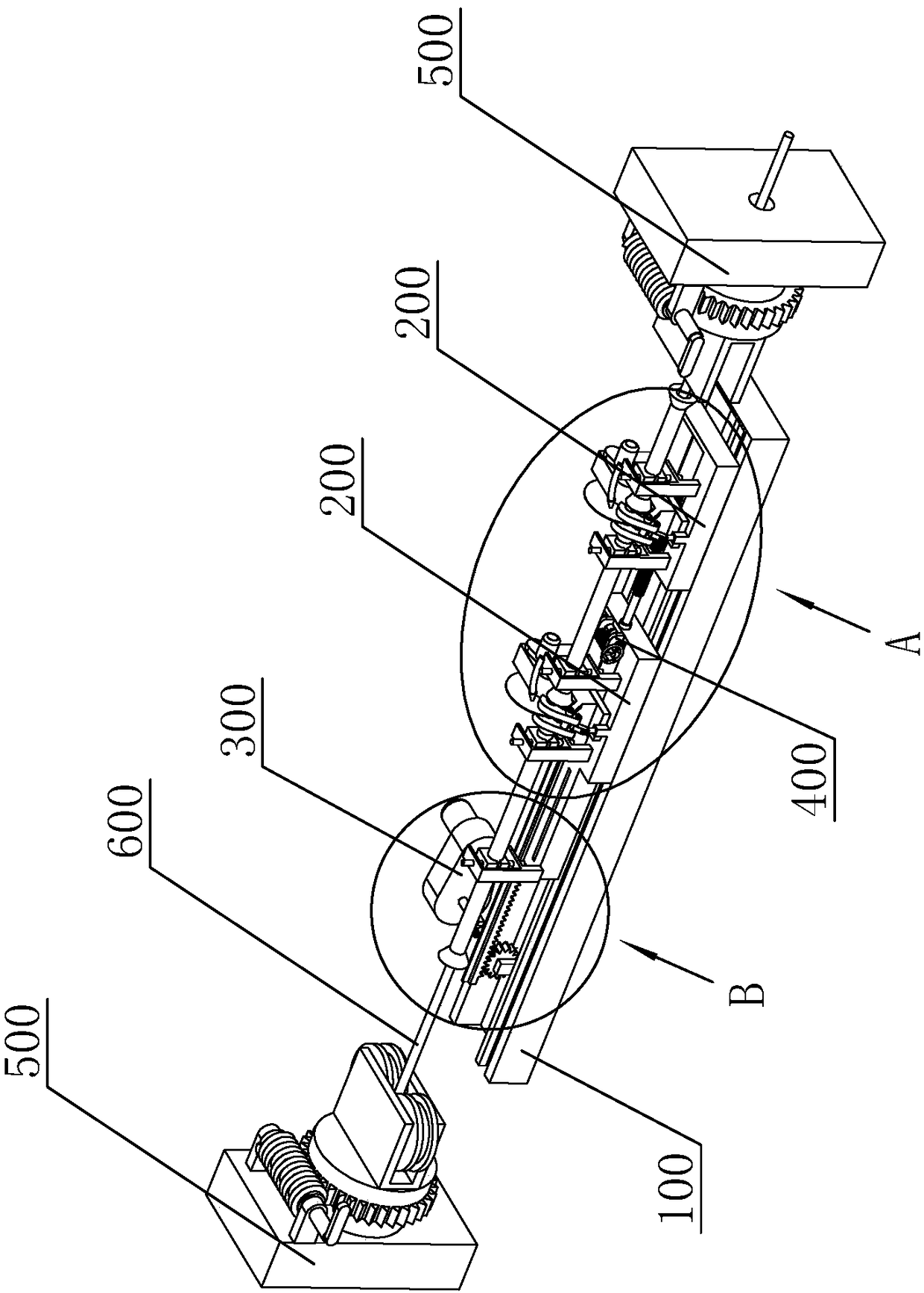
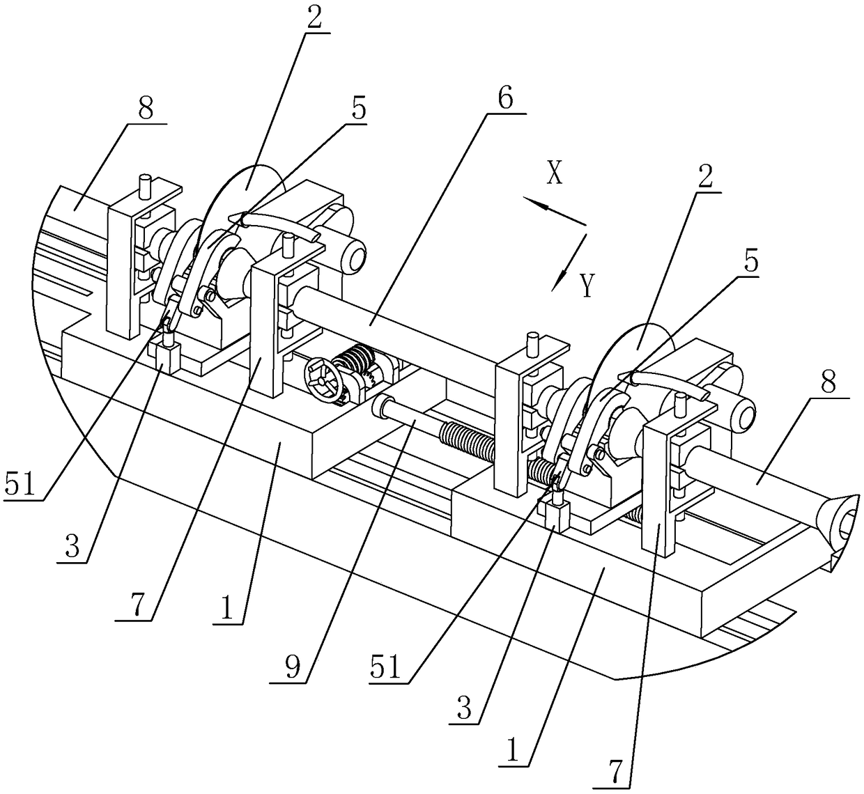
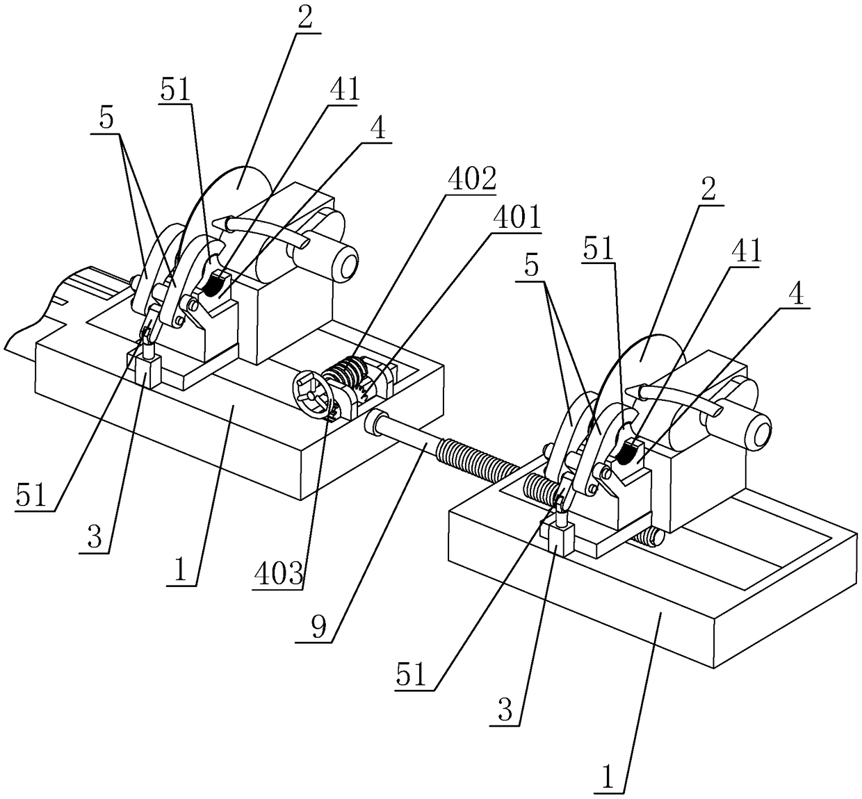
[0036] Such as figure 1 and figure 2 As shown, the CNC double flying saw cold cutting machine of the present invention includes a workbench 100, two sets of flying saw devices 200 slidably arranged on the workbench 100, a traverse drive unit 300, a distance adjuster 400 and a guide Wheel device 500.

[0037] The two sets of flying saw devices 200 are connected to each other through the adjustable screw rod 9, and are driven by the traversing drive unit 300 to slide synchronously on the workbench 100 left and right. A pulley that is slidably matched with the slide rail is provided, and the axis of the screw rod 9 and the lateral movement direction of the flying saw device 200 ( figure 2 X direction shown in ), one end of the screw rod 9 is rotatably arranged on the base 1 of one of the flying saw devices 200, and the base 1 of the other flying saw device 200 is fixed with a nut thr...


PUM


Abstract

The invention relates to the field of metal tube machining equipment, in particular to a using method of a numerical control dual-flying-saw cold slitting machine. The method is characterized by comprising the following steps that 1, a metal tube is conducted by a guide wheel device to enter a guiding tube and a conveying tube close to a feeding end; 2, the metal tube is clamped between gaps of arocker arm and a fixing block; 3, feeding mechanisms on two sets of flying saw devices simultaneously drive flying saws to move in the cutting direction and cut the metal tube, and two metal tubes ofthe needed length are cut out; 4, the two sets of flying saw devices move towards the feeding end, in the moving process, the metal tube to be slit at the feeding end abuts against the slit metal tube, the slit metal tube is forced to move towards the guiding tube at a discharging end and finally is conveyed outside. Within each working period, two metal tubes can be cut and produced, the production efficiency is greatly improved, the interval between the two sets of flying saw devices is adjusted through a screw, and the needed cutting length can be freely regulated.

Description

[0001] This application is a divisional application of the original application of a CNC dual-flying saw cold cutting machine with an application date of October 27, 2016, an application number of 201610956818.X, and an invention title. technical field [0002] The invention relates to the field of metal pipe processing equipment, in particular to a method for using a numerical control double flying saw cold cutting machine. Background technique [0003] Common flying saws are divided into cold-cut saws and hot-cut saws. Ordinary flying saws are tungsten steel saw blades that rotate at high speed, and contact with welded pipes to generate heat to make them disconnect. The high-speed steel saw blade rotates slowly and mills off the welded pipe, so it can be burr-free and noise-free, gradually replacing traditional manual cutting, and has high production efficiency. [0004] As shown in the invention patent application with the application publication number CN103386506A, an a...

Claims


Application Information

Patent Timeline
Patent Type & Authority Applications(China)
IPC IPC(8): B23D45/20B23D45/12
CPCB23D45/12B23D45/20
Inventor 张伟萍
Owner 晋江市伟业城金属制品有限公司
Why Eureka
Try Eureka