Shell boring, milling and drilling equipment

A drilling equipment, boring and milling technology, applied in the field of production and manufacturing of intelligent processing equipment, can solve problems such as complex shape and high processing ratio, and achieve the effect of avoiding multiple processing and forming, saving time and reducing costs

Inactive Publication Date: 2018-11-30
深圳市中科创想科技有限责任公司
View PDF0 Cites 0 Cited by
  • Summary
  • Abstract
  • Description
  • Claims
  • Application Information

AI Technical Summary

Problems solved by technology

Therefore, the invention is very beneficial for a kind of CNC machine tool with complex shape, relatively large machining ratio, and relatively high precision requirements. Therefore, there are defects in the prior art and need to be improved.

Method used


Image

  • Shell boring, milling and drilling equipment

Examples


Embodiment 1

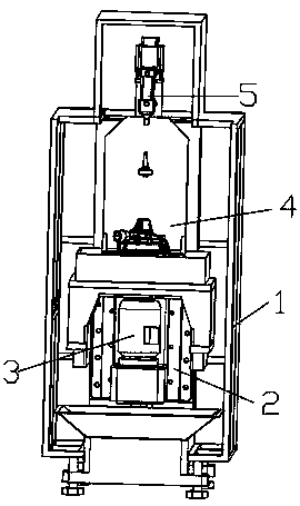
[0040] For a shell with a regular shape, place the shell on the movable fixture base 2, fix the movable fixture, stop the fixture base on the alignment platform, and automatically adjust the alignment platform to meet the alignment requirements, and then perform drilling.

Embodiment 2

[0042] For shells with irregular shapes, place the shell on the base of the movable fixture, and simulate it with a computer simulation device. The lifting device grabs the shell through mechanical claws, adjusts the position of the mounting plate at the same time, and positions it through the CCD positioning system; If there is no need, confirm whether the telescopic rod is installed according to the telescopic rod; if there is no hole, install the connecting rod, then determine the fixed position, and then adjust the shape of the vacuum capsule, adjust the position of the telescopic rod, and adjust it through the moving device on the power unit. Fixed; at the same time withdraw the movable clamp base.

[0043] For shells with irregular shapes, place the shell on the base of the movable fixture, and simulate it with a computer simulation device. The lifting device grabs the shell through mechanical claws, adjusts the position of the mounting plate at the same time, and positio...

Embodiment 3

[0045] According to the structure and size of the shell, select the number of segments to use the telescopic rod, and also select the size of the corresponding hollow cylinder according to the size of the aperture. On the mounting plate, various types of telescopic rods are provided for optional use.

[0046] For example telescopic rod is provided with six sections, then has five hollow cylinders and a center cylinder, and the outermost layer is the first section, and then the center cylinder is the sixth connection, also has five groups of solid cylinders 7 simultaneously, and the outermost is the first section. One group, followed by the second group, third group, fourth group and fifth group. When it is necessary to use the fifth joint to extend the three joints, the transmission device automatically selects the fourth group of solid cylinders 7, and by rotating the transmission, the fifth joint and the sixth joint protrude together, and stop when the specified length is re...


PUM


Abstract

The invention discloses shell boring, milling and drilling equipment. The shell boring, milling and drilling equipment comprises an outer cover, a machine body, a body milling power device, a formingtool assembly, a movable clamp assembly and a cleaning assembly. An outer cover frame is arranged in the outer cover. An installing plate is fixed to the outer cover frame. The machine body is arranged at the lowest outer cover frame. The body milling power device, the movable clamp assembly and the cleaning assembly are sequentially arranged in the outer cover and above the machine body. The forming tool assembly is arranged on the body milling power device. The shell boring, milling and drilling equipment conducts accurate fixing on various shells, automatic position detection can be achieved, the accurate production requirement is met, multi-time machining forming is avoided, the time is saved, and cost is reduced. In addition, in the drilling process, since positioning is accurate, thedrilling precision and the relative position are more accurate; and meanwhile, direct stepped hole production is achieved, the inner stepped hole production manner that multi-time machining is adopted, and then combination is conducted is rejected, rapidness and one-time production are achieved, and market competiveness is improved.

Description

technical field [0001] The invention relates to the production and manufacture of intelligent processing equipment, in particular to a casing boring, milling and drilling equipment. Background technique [0002] At present, most of the known machine tools only have one function. For example, milling machines only have the function of milling, grinding machines only have the function of grinding, and it is difficult to process complex shapes. Multi-process operations are required to achieve the final shape or quality requirements. It needs to be processed on different machine tools in sequence, repeated clamping is required, the processing efficiency is low, and the processing quality of parts is unstable. Especially when processing large parts with irregular shapes, it is necessary to produce a shape with certain rules or auxiliary functions, which must be processed continuously during production, and then the final shape is formed. This deficiency is particularly obvious. ...

Claims


Application Information

Patent Timeline
Patent Type & Authority Applications(China)
IPC IPC(8): B23P23/02
CPCB23P23/02
Inventor 钟建春
Owner 深圳市中科创想科技有限责任公司
Why Eureka
Try Eureka