Optical glass mirror grinding equipment

A technology of optical glass and equipment, which is applied in the field of optical glass mirror grinding equipment, can solve the problems of not being able to guarantee the grinding accuracy and being on the same straight line, and achieve the effects of convenient grinding, improving precision and avoiding optical performance

Active Publication Date: 2020-06-23
XINYI DONGFANG SHUOHUA OPTICAL MATERIALS CO LTD
View PDF5 Cites 2 Cited by
  • Summary
  • Abstract
  • Description
  • Claims
  • Application Information

AI Technical Summary

Problems solved by technology

[0005] In the above patent document 1, the glass to be polished is manually placed on the vacuum chuck with the axis of the rotating motor as the center. This cannot ensure that the center of the glass to be polished is on the same line as the axis of the motor, and the grinding accuracy cannot be guaranteed.

Method used


Image

  • Optical glass mirror grinding equipment
  • Optical glass mirror grinding equipment
  • Optical glass mirror grinding equipment

Examples


Embodiment Construction

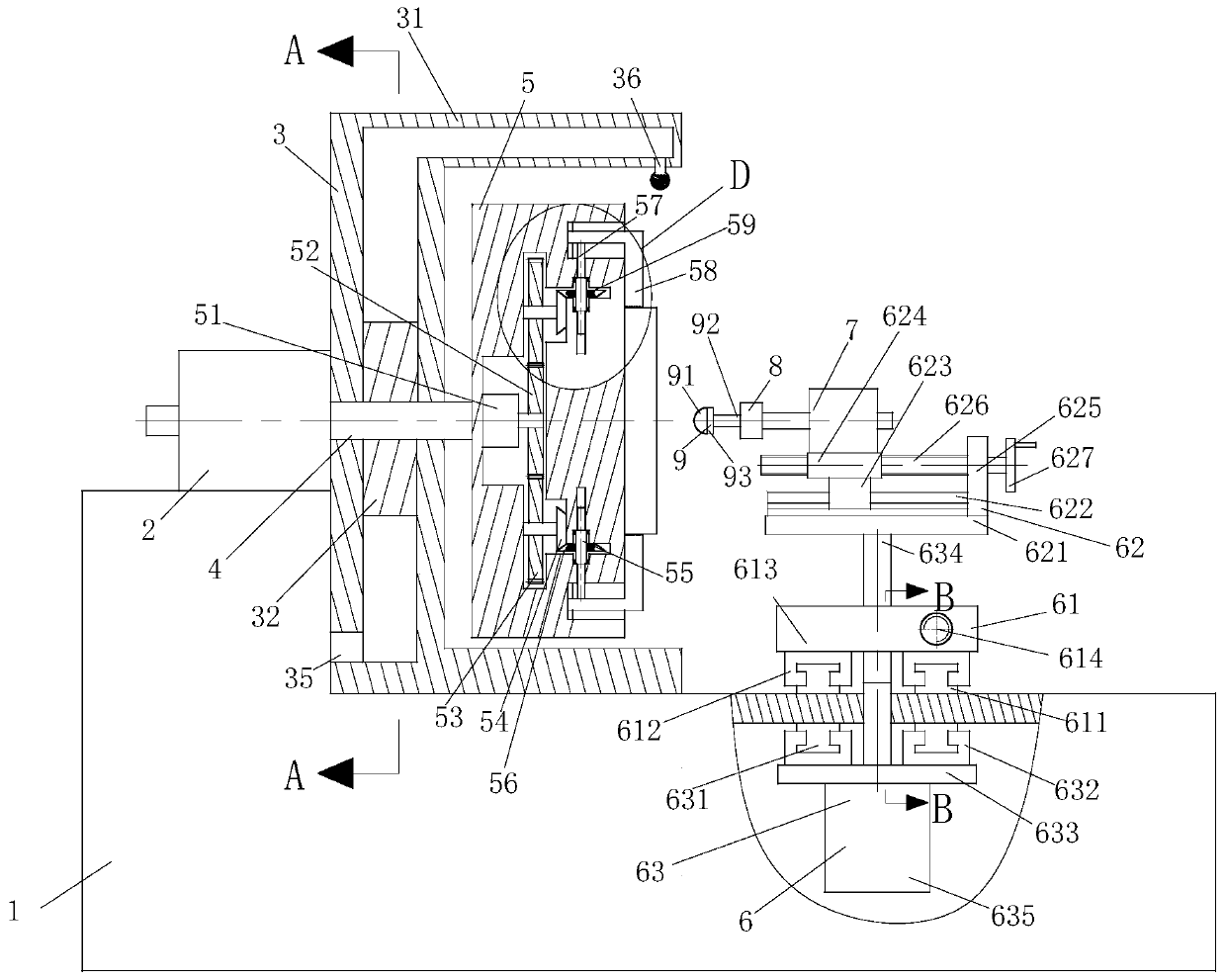
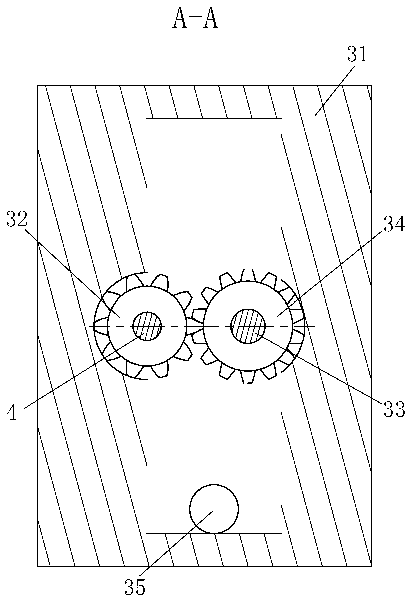
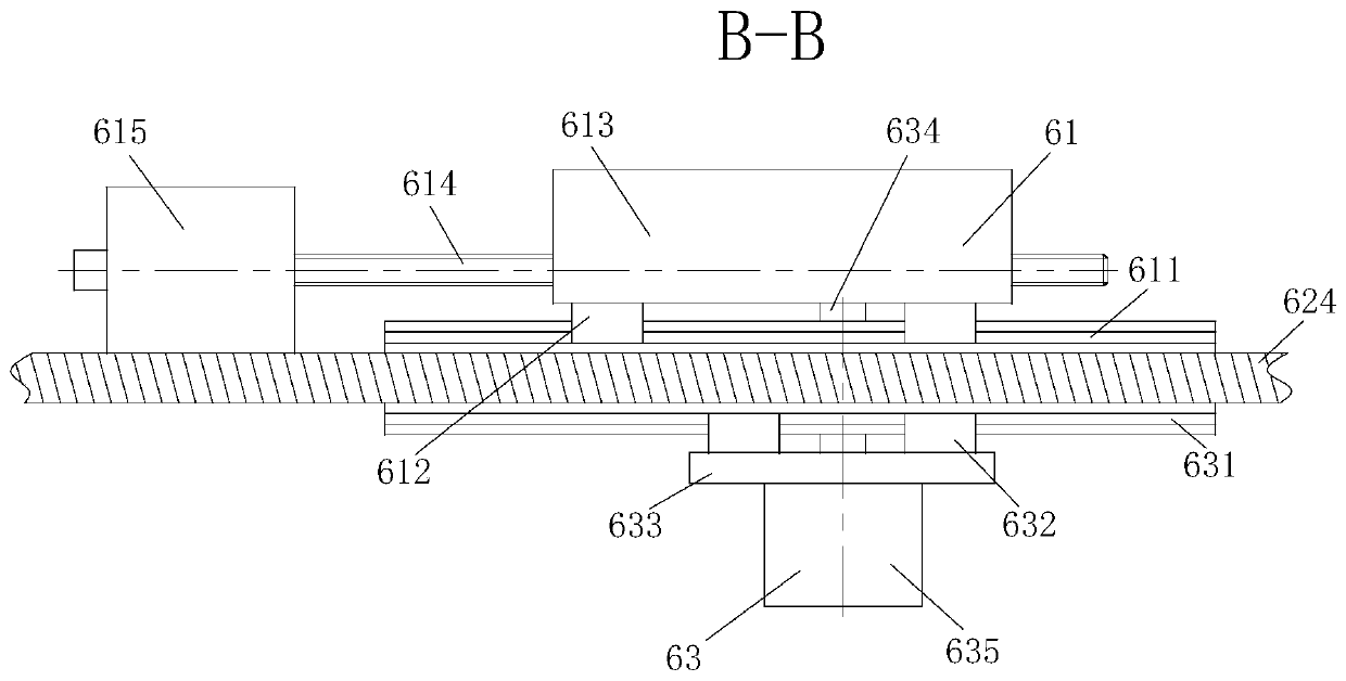
[0030] use Figure 1-Figure 9 The structure of an optical glass mirror polishing device according to an embodiment of the present invention will be described as follows.

[0031] Such as figure 1 , Figure 5 and Figure 6 As shown, a kind of optical glass mirror grinding equipment according to the present invention includes a base 1, a motor 2, a spray module 3, a connecting shaft 4, a fixing seat 5, a position adjustment module 6, a motor 2 7, and a connecting seat 8 and the grinding head 9; the motor one 2 is fixed on the base 1, and the motor one 2 is located at the right end of the base 1; the spray module 3 is fixed on the base 1, and the spray module 3 is located on the base 1 On the right side, the spray module 3 is used to cool the optical glass during processing, and the spray module 3 can also remove the debris on the optical glass, eliminating the influence of glass debris; the left end of the connecting shaft 4 Pass through the spray module 3 and fix on the out...


PUM


Abstract

The invention belongs to the technical field of production of optical glass, and particularly relates to optical glass mirror plane polishing equipment. The optical glass mirror plane polishing equipment comprises a machine base, a first motor, a spraying module, a first connection shaft, a fixed seat, a position adjusting module, a second motor, a connection seat and a polishing head; the first motor is fixed to the machine base, and located at the right end of the base; the spraying module is fixed to the machine base, and located at the right side of the machine base, and the spraying module is used for cooling the optical glass in the processing process; the left end of the first connection shaft penetrates through the spraying module and is fixed to the output shaft of the first motor; the fixed seat is fixed to the right end of the first connection shaft, and used for fixing the optical glass; the position adjusting module is located on the right side of the fixed seat, and fixedto the machine base; the second motor is fixed to the top of the position adjusting module; the connection seat is fixed to the left side of the motor through the output shaft of the motor; and the polishing head is mounted at the left end of the connection seat.

Description

technical field [0001] The invention belongs to the technical field of optical glass production, in particular to an optical glass mirror polishing equipment. Background technique [0002] The commonly defined optical glass refers to glass materials used to manufacture lenses, prisms, mirrors, windows, etc. of optical instruments or mechanical systems. There are many kinds of optical glass, including colorless optical glass, colored optical glass, laser glass, radiation-resistant optical glass, radiation-resistant optical glass, glass-ceramic, electronic glass and optical quartz glass, etc., with more and more uses. Some functional glass materials are also included. [0003] Grinding is divided into coarse grinding and fine grinding, both of which play an important role in optical glass processing. With the development of society, people have higher and higher requirements for optical glass. The existing optical glass mirror grinding The processing accuracy of the equipmen...

Claims


Application Information

Patent Timeline
Patent Type & Authority Patents(China)
IPC IPC(8): B24B13/00B24B13/005B24B55/02B24B41/04B24B27/00B24B41/02B24B55/00B24B47/04
CPCB24B13/00B24B13/0055B24B27/0076B24B41/02B24B41/04B24B47/04B24B55/00B24B55/02
Inventor 程春丽
Owner XINYI DONGFANG SHUOHUA OPTICAL MATERIALS CO LTD
Why Eureka
Try Eureka