Machine drilling end reaming drill bit special for filling pile, and construction method thereof

A cast-in-place pile and tip technology, which is applied to drill bits, sheet pile walls, drilling equipment, etc., can solve problems such as large gaps, uncertain sizes, and inability to adapt to the adjustment of reaming diameters, so as to reduce the possibility of damage and reduce The effect of cost consumption

Active Publication Date: 2018-11-30
四川锦城智信建设工程有限公司
5 Cites 15 Cited by

AI-Extracted Technical Summary

Problems solved by technology

However, when the special drill bit is reaming, the force exerted by the bottom wall of the hole on the drill bit is uncontrollable, that is, the angle between the bar tool holders is uncertain, so that the hole diameter afte...

Method used

Adjust the process between adjustments: the operator moves the sliding bar 42 so that the limiting hole 421 on the sliding bar 42 is aligned with the required adjusting hole 411, and now the bolt is passed through the adjusting hole 411 and the limiting hole 421, and Turn the nut to fix the relative position between the current adjusting rod 41 and the bolt, and now the adjustment is completed. The setting of the adjustment part 4 enables the special drill bit to ream the aperture within a certain range, r...

Abstract

The invention relates to a machine drilling end reaming drill bit special for a filling pile, and a construction method thereof, and belongs to the technical field of filling piles. The machine drilling end reaming drill bit comprises a reducer union connected with a drill rod, and a plurality of cutter frames. The cutter frames comprise two strip-shaped cutter frames which are mutually hinged. The machine drilling end reaming drill bit further comprises an adjusting piece. The adjusting piece comprises an adjusting rod and a sliding rod. One end of the adjusting rod is connected with the strip-shaped cutter frames, and connecting points are located on the strip-shaped cutter frames hinged to the reducer union. The sliding rod is sleeved with the adjusting rod. Outer sleeving rods are provided with a plurality of adjusting holes in the axial direction of the outer sleeving rods. The sliding rod is provided with a limiting hole. Fixing pieces used for limiting the total length of the adjusting piece are arranged at the adjusting holes and the limiting hole in a penetrating mode. When the drilling diameter of the special drill bit is changed, an operator fixes the fixing pieces to the different adjusting holes, and thus the diameter of a reamed hole can be changed by changing the total length of the adjusting piece.

Application Domain

Drill bitsBulkheads/piles

Technology Topic

EngineeringDrill bit +2

Image

  • Machine drilling end reaming drill bit special for filling pile, and construction method thereof
  • Machine drilling end reaming drill bit special for filling pile, and construction method thereof
  • Machine drilling end reaming drill bit special for filling pile, and construction method thereof

Examples

  • Experimental program(2)

Example Embodiment

[0040] Embodiment one:
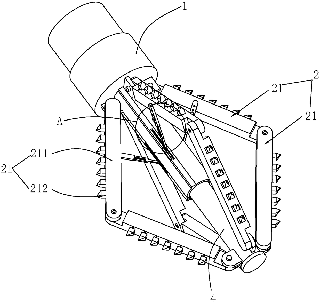
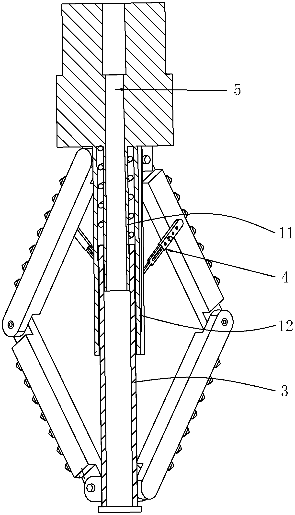
[0041] like figure 1 , 2 As shown, a special special drill bit for cast-in-situ pile reaming with machine drill ends, including a reducing joint 1 connected with a drill rod and a plurality of tool holders 2, and the number of tool holders 2 is set to four in this embodiment. The side wall of the variable diameter joint 1 away from the drill pipe is provided with an inner sleeve rod 11 and an outer sleeve rod 12, the outer sleeve rod 12 is sleeved outside the inner sleeve pipe, and a guide rod 3 is movable between the inner sleeve rod 11 and the outer sleeve rod 12 to guide A spring is connected to one end of the rod 3 between the inner sleeve rod 11 and the outer sleeve rod 12 , and the other end of the spring is connected to the reducing joint 1 .
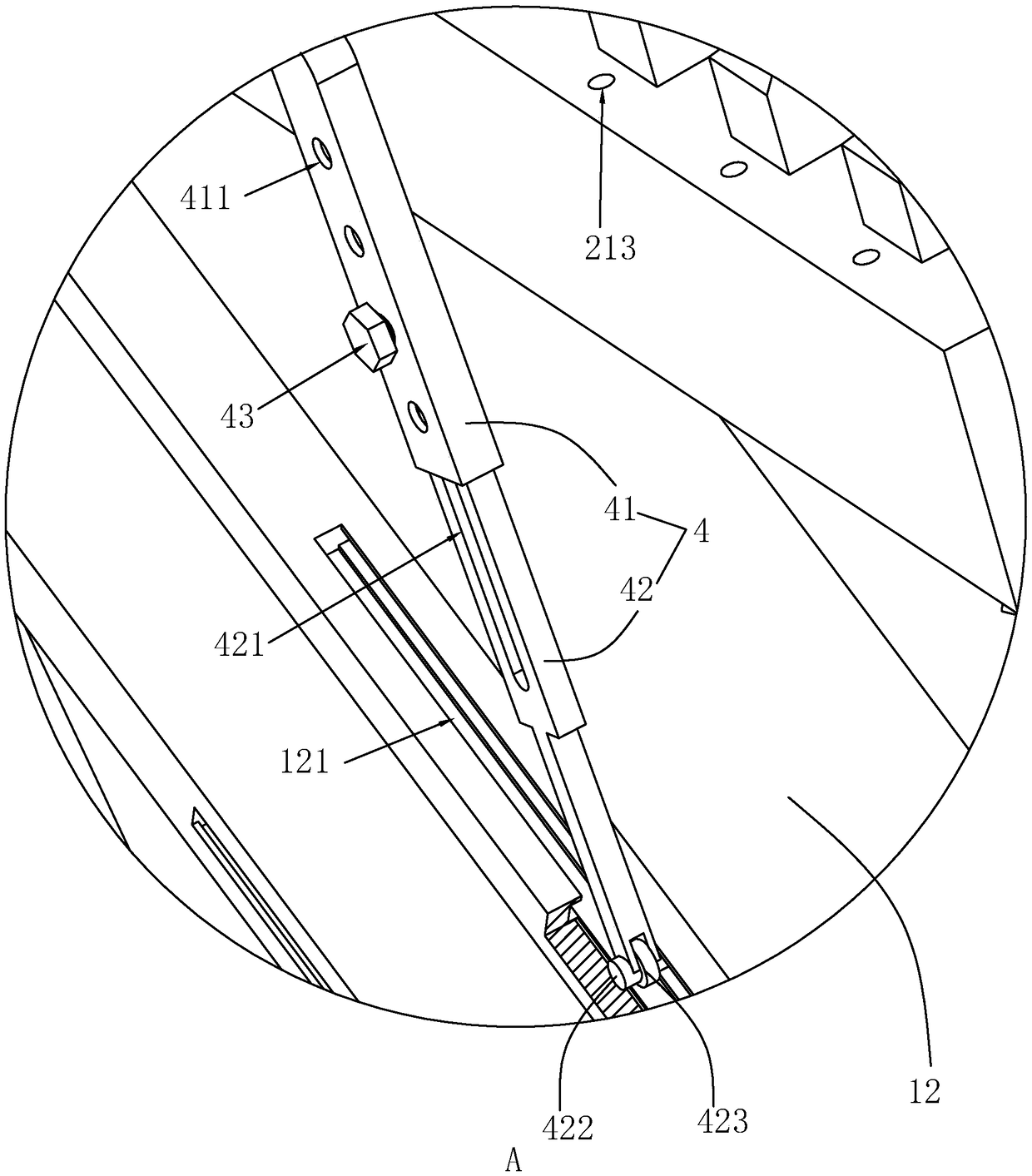
[0042] like figure 1 , 2 As shown, one end of the tool holder 2 is hinged with the side wall of the inner sleeve rod 11 provided with the reducing joint 1, and the other end is hinged with the guide rod 3 and the hinge point is set away from the reducing joint 1. The tool holder 2 includes two mutually hinged bars Shaped knife rest 212, also comprises adjusting member 4, and adjusting member 4 comprises adjusting rod 41 and slide bar 42, and one end of adjusting rod 41 is connected with bar-shaped knife rest 212 and the connecting point is at the bar-shaped knife rest hinged with variable diameter joint 1 212, the adjustment rod 41 is sleeved on the slide rod 42, and the outer sleeve rod 12 is provided with a plurality of adjustment holes 411 along its axial direction. All are marked with the diameter of the hole dug by the special drill bit. The sliding rod 42 is provided with a waist-shaped limiting hole 421 , and the adjusting hole 411 and the limiting hole 421 are pierced with a fixing member 43 for limiting the total length of the adjusting member 4 . In this embodiment, the fixing member 43 is configured as a bolt with one end passing through the limiting hole 421 and the adjusting hole 411 and a nut threadedly connected with the bolt. In other embodiments, the fixing member 43 can also be configured as a pin.
[0043] likefigure 1 , 2 As shown, the outer casing rod 12 is provided with a chute 121 with an inverted T-shaped cross section along its axial direction, and the end of the sliding rod 42 away from the adjustment rod 41 is provided with a roller 423 and the roller 423 is in the chute 121 and moves along the chute 121, The sliding rod 42 is provided with an anti-off block 422 that reduces the separation between the sliding rod 42 and the slide groove 121 .
[0044] The process of adjusting the adjustment room: the operator moves the sliding rod 42 so that the limiting hole 421 on the sliding rod 42 is aligned with the required adjusting hole 411. At this time, the bolt is passed through the adjusting hole 411 and the limiting hole 421, and the screw nut is fixed. The relative position between the current adjusting rod 41 and the bolt is now adjusted. The setting of the adjusting part 4 enables the special drill bit to expand the aperture within a certain range, reducing the phenomenon of changing different special drill bits when holes with different diameters need to be expanded, and reducing the cost of use.
[0045] The working process of the special drill bit: when the special drill bit rotates, under the action of the centrifugal force and the support force of the hole bottom wall to the guide rod 3, the angle between the two shaped tool holders 212 becomes smaller, and at this time the roller 423 moves along the direction of the chute 121 , when the roller 423 moves to the end of the chute 121 and the adjustment member 4 is stretched to the longest length, the adjustment member 4 no longer moves, and the angle between the two shaped tool rests 212 is determined by the tension of the adjustment member 4 and the rotation of the special drill bit. Under the action of centrifugal force, the angle is fixed, and the diameter of the reamed hole is determined at this time.
[0046] like figure 1 , 3 As shown, the guide rod 3 and the reducing joint 1 are provided with a water channel 5 , and the guiding rod 3 is communicated with the water channel 5 of the reducing joint 1 . Described strip knife rest 212 comprises knife bar 211 and knife head 212, and knife bar 211 is all provided with spray hole 213 and knife head 212 on the side wall away from guide bar 3, spray hole 213 and knife bar 211 are on the same horizontal line and The spray hole 213 communicates with the water channel 5 .
[0047] When the special drill bit is working, the water delivered to the water channel 5 is sprayed from the nozzle hole 213, and impacts the expanded hole wall, and the compact structure of the hole wall is partially destroyed under the action of the water pressure, so that the cutter head 212 is It is more convenient when digging.
[0048] When the special drill bit is working, the cutter head 212 rubs against the soil, so that the temperature of the cutter head 212 increases, and the water sprayed from the nozzle hole 213 cools the cutter head 212 to reduce the probability of the cutter head 212 being damaged.

Example Embodiment

[0049] Embodiment two:
[0050] A construction method of a cast-in-place pile with a machine-drilled end reaming is carried out according to the following steps:
[0051] a) The operator uses a bulldozer to initially level the site, and then the operator positions the cast-in-place piles according to the construction drawings. After the positioning is completed, use the pile position counter to determine the position of the casing.
[0052] b) Put the side wall of the casing against the side wall of the pile position counterpointer. At this time, the point to be punched is at the center of the casing, and pressure is applied on the side wall of the casing away from the ground to make one end of the casing 50cm into the ground, the casing should be set vertically at this time, and the deviation should be corrected in time when the position of the casing is deviated; Drill holes at the predetermined points and construct to the predetermined reaming depth.
[0053] c) Manually excavate the mud pool near the casing while drilling with an ordinary machine drill, and set a filter device in the middle of the mud pool so that the mud pool is divided into an unfiltered chamber and a filtered chamber. In this embodiment, no The filter cavity is set close to the casing, and the liquid in the drilled hole that has diffused to the level above the ground in the casing is introduced into the unfiltered cavity, and the liquid in the unfiltered cavity is filtered by the filter device and then enters the filtered cavity for further processing. Temporarily stored, and pumped through the pipeline by the water pump to the ordinary machine drill for recycling.
[0054] When the conventional machine drill reaches the predetermined reaming depth, stop drilling and wait for the replacement of the special drill bit; the operator adjusts the diameter of the hole that the special drill bit can process and installs it on the drill pipe. The diameter of the hole processed by the special drill bit can be adjusted so that the special drill bit can adapt to the requirements of different hole diameters, reducing the use of different drill bits to process holes with different hole diameters, and reducing cost consumption.
[0055] d) The operator installs the special drill bit and drills the hole.
[0056] e) After the reaming is completed, the operator takes out the special drill bit, injects concrete slurry into the hole, waits for the concrete slurry to solidify, and the operator dismantles the casing after the concrete solidifies.

PUM

no PUM

Description & Claims & Application Information

We can also present the details of the Description, Claims and Application information to help users get a comprehensive understanding of the technical details of the patent, such as background art, summary of invention, brief description of drawings, description of embodiments, and other original content. On the other hand, users can also determine the specific scope of protection of the technology through the list of claims; as well as understand the changes in the life cycle of the technology with the presentation of the patent timeline. Login to view more.

Similar technology patents

An operation method of radio frequency identification reader

ActiveCN109711214Areduce collisionReduce cost consumption
Owner:PROMOS TECH INC

Image-based parameter filling terminal and method

InactiveCN111556356AGuaranteed correctnessReduce cost consumption
Owner:CHONGQING JINMEI COMM

Lateral-emission type backlight module and display device

ActiveCN107561774Aincrease profitReduce cost consumption
Owner:SHENZHEN SKYWORTH RGB ELECTRONICS CO LTD

Method for managing planned receiving, transmitting and storing information of production auxiliary materials

PendingCN113420956AReduce inventory backlogReduce cost consumption
Owner:BAOTOU IRON & STEEL GRP

Processing technology of mixed amine

InactiveCN113185413AReduce consumption of raw materialsreduce cost consumption
Owner:宁波乐维实业有限公司

Classification and recommendation of technical efficacy words

  • reduce cost consumption
  • reduce the possibility of damage

Bidirectional transmission conversion device and transmission method thereof

ActiveCN111911556AClutch structure is simpleReduce cost consumption
Owner:软丰科技(江苏)有限公司淮安分公司

Large-view-field high-flux high-resolution pathological section analyzer

PendingCN112712877AReduce cost consumptionAvoid errors
Owner:XIDIAN UNIV

Conjoined double-cavity mould

InactiveCN103465397Areduce cost consumptionReduce the number of mold changes
Owner:SUZHOU YIQUN MOLD

Ionic membrane electrolytic bath

ActiveCN103469245Areduce the possibility of damageExtended service life
Owner:BLUESTAR BEIJING CHEM MACHINERY

Semiconductor structure forming method

InactiveCN107785316AReduce the impactreduce the possibility of damage
Owner:SEMICON MFG INT (SHANGHAI) CORP +1

Mold display device for mathematics education

InactiveCN110074611AImprove the protective effectreduce the possibility of damage
Owner:YANAN UNIV

Refrigerator and shelf assembly

InactiveCN104880009Areduce the possibility of damageSimple structure
Owner:HUBEI MIDEA REFRIGERATOR CO LTD +1

Air conditioner and running method of air conditioner

InactiveCN106940057AGuaranteed defrosting reliabilityreduce the possibility of damage
Owner:GREE ELECTRIC APPLIANCES INC OF ZHUHAI
Why Eureka
Try Eureka