
Method for optimizing oil layer pressure plugging and displacement technical modes

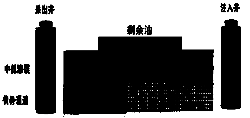
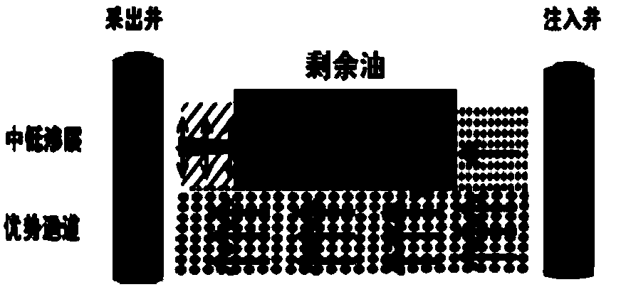
A process and mode technology, applied in the field of oil layer plugging and flooding process mode selection, can solve problems such as inability to effectively tap the remaining oil in complex well groups, and achieve the effect of avoiding incompatibility

Active Publication Date: 2018-11-30
DAQING OILFIELD CO LTD +1
View PDF5 Cites 3 Cited by
  • Summary
  • Abstract
  • Description
  • Claims
  • Application Information

AI Technical Summary

Problems solved by technology

[0012] In view of this, the present invention provides an optimal method for oil reservoir pressure plugging and flooding process mode, which is suitable for effective displacement of remaining oil in complex well groups, and solves the current technical mode of oil well pressure plugging or oil well pressure flooding for a single well The problem of not being able to effectively tap the remaining oil in complex well groups

Method used


Image

  • Method for optimizing oil layer pressure plugging and displacement technical modes
  • Method for optimizing oil layer pressure plugging and displacement technical modes
  • Method for optimizing oil layer pressure plugging and displacement technical modes

Examples


Embodiment 1

[0071] The experimental well is well B1-6-P68 in the Changyuan I oil layer of Daqing.

[0072] Well B1-6-P68 is an old production well after polymer flooding, and it was drilled on October 10, 1996. The oil-water well spacing of this well is 175m, the well depth is 1166.71m, and the perforated section depth is 1068.9-1097.7m. A total of 8 sublayers from PI1 to PI7 are perforated, including PI2 sublayer.

[0073] (1) Target well group data preparation

[0074] Well Group Reservoir Development

[0075] The target well group is located at the edge of the horizontal well group experiment area, with an oil well in the middle and 6 injection wells around it. The mining target layer of this well belongs to the river-delta sedimentary system, and the PI2 unit belongs to the high-bending large-scale compound meandering river sediment of the floodplain facies, and the reservoir point bar sand body is well developed.

[0076] It can be seen from the detailed description of the sand ...

Embodiment 2

[0089] The experimental well is the L9-PS2133 well in the Changyuan I oil layer in Daqing.

[0090] Well L9-PS2133 is an old production well after polymer flooding, and its drilling was completed on January 4, 2008. The oil-water well spacing of this well is 150m, the well depth is 1141.10m, and the perforation section depth is 1014.8~1035.2m, and a total of 5 sublayers from SIII3 to 10 are perforated, including SIII3-7 sublayers.

[0091] (1) Target well group data preparation

[0092] Well Group Reservoir Development

[0093] The target well group is located in Well L9-PS2133, which is located in the Northeast Block 1 of Lamadian Oilfield, with a block area of ​​7.1 km2, where SIII3-10 is exploited, and SIII3-7 layers are continuous channel sand bodies with good porosity and permeability conditions, belonging to a kind of reservoir.

[0094] It can be seen from the detailed description of the sand body development of the well group reservoirs that the SIII3-7 unit of We...


PUM


Abstract

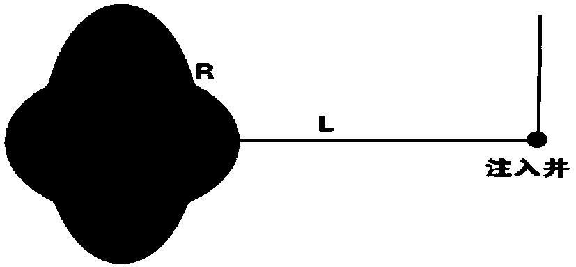
The invention discloses a method for optimizing oil layer pressure plugging and displacement technical modes. According to the method, according to data such as well group reservoir development, wellnetwork conditions, development status, residual oil distribution situations and water flooded layer interpretation, the high water flooding invalid circulation part of a well group is determined, theseven pressure plugging and displacement construction technical modes are put forward, condition judging is conducted according to the simple invalid circulation part and the residual oil distribution situations, and a target reservoir single well or the well group are quickly matched with the reasonable 'pressure plugging and displacement' construction technical modes. The problem that at present, by adopting the technical mode of oil well pressure plugging or oil well pressure displacement for a single well, potential tapping cannot be effectively conducted on residual oil of a complex wellgroup is solved.

Description

technical field [0001] The invention relates to the technical field of petroleum exploitation, in particular to a method for selecting an oil layer pressure plugging and flooding process mode. Background technique [0002] At present, after the development of chemical flooding, the main oil layers of some oilfields in China have a recovery rate of more than 50% and a comprehensive water content of more than 95%. Highly permeable and strongly water-washed strips, the heterogeneity of the oil layer in the longitudinal direction is more serious. In the subsequent water flooding development process, a strong water wash strip is formed at the bottom of the oil layer, and the low-efficiency and ineffective circulation are serious, resulting in the remaining oil remaining at the top of the positive rhythm oil layer or the low water wash part in the middle and upper part of the compound rhythm oil layer. [0003] At present, some oilfields have proposed fracturing plugging technolo...

Claims


Application Information

Patent Timeline
IPC IPC(8): E21B43/16E21B43/26E21B33/13
CPCE21B33/13E21B43/16E21B43/26
Inventor 万军孙智闫鸿林汪玉梅金岩松李卓张新珠杨光李扬成官联轲
Owner DAQING OILFIELD CO LTD
Learn More