Chemical conveying pipe for heat supply

A technology for transporting pipes and pipes, which is applied in the directions of pipe heating/cooling, pipes/pipe joints/pipes, mechanical equipment, etc., can solve the problems of increasing assembly difficulty, high production cost, low efficiency, etc. Heat supply efficiency, improve the effect of heat supply

Inactive Publication Date: 2018-11-30
FOSHAN KUIFENG BUSINESS CONSULTATION SERVICES CO LTD
View PDF0 Cites 2 Cited by
  • Summary
  • Abstract
  • Description
  • Claims
  • Application Information

AI Technical Summary

Problems solved by technology

[0003] 1. The chemical transmission pipelines used to supply heat in the prior art will be equipped with a large number of temperature sensors when supplying heat to the transported substances, which greatly increases the production and assembly burden and increases the production cost in the manufacturing process. At the same time, the difficulty of assembly is increased, and when transporting such substances, only a certain amount of heat needs to be provided to ensure the normal transmission of the substances. In contrast, the current chemical transmission pipelines for supplying heat make the design of the heating system too complicated, which greatly improves the The input cost of small and medium-sized enterprises cannot effectively meet the needs of existing technologies
[0004] 2. Due to the structural defects of the heat supply chemical transmission pipeline in the prior art when transferring substances and supplying heat, the heating and stirring rod provided by itself is petite during heat transfer, and the efficiency is too low when stirring , cannot effectively make the transported substance get enough heat, so it cannot meet the requirements of the existing technology

Method used


Image

  • Chemical conveying pipe for heat supply
  • Chemical conveying pipe for heat supply
  • Chemical conveying pipe for heat supply

Examples


Embodiment Construction

[0025] The following will clearly and completely describe the technical solutions in the embodiments of the present invention with reference to the accompanying drawings in the embodiments of the present invention. Obviously, the described embodiments are only some, not all, embodiments of the present invention. Based on the embodiments of the present invention, all other embodiments obtained by persons of ordinary skill in the art without making creative efforts belong to the protection scope of the present invention.

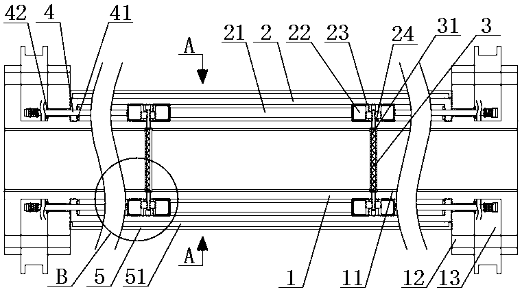
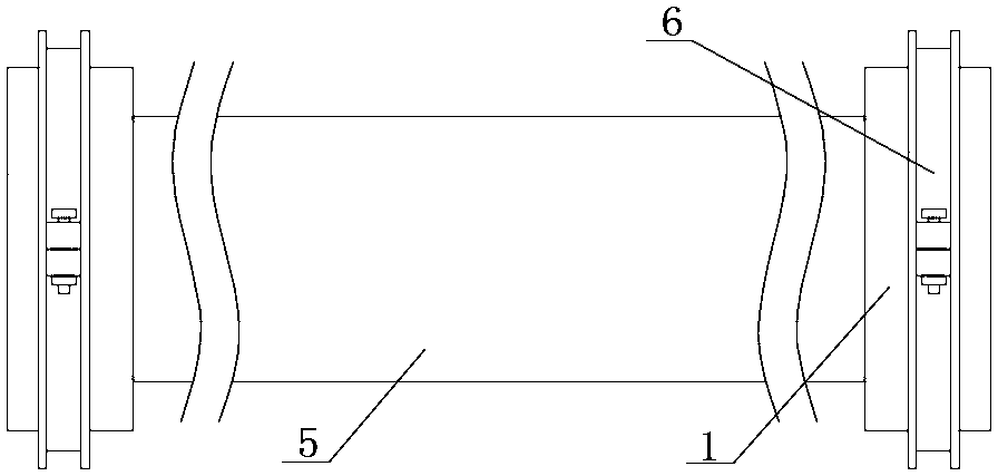
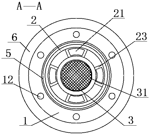
[0026] see Figure 1-5 , the present invention provides a technical solution: a chemical transmission pipeline for heat supply, including a pipeline body 1, a fixed cover 2, a ring bracket 31, a joint cable 4 and a protective cover 5, characterized in that: the pipeline body 1. The inner wall is welded with an inner wall protective layer 11, which not only protects the pipeline body 1, but also plays an auxiliary role in limiting the heat transfer end of the h...


PUM


Abstract

The invention discloses a chemical conveying pipe for heat supply. The chemical conveying pipe for heat supply comprises a pipe body, a fixed cover, an annular bracket, a joint cable and a protectivecover; an inner wall protecting layer is welded on the inner wall of the pipe body; the fixed cover is welded at the middle part of the periphery of the pipe body; heaters are fixedly connected between the inner wall of the fixed cover and the periphery of the pipe body and near two ends through bolts; heat conveying ends of the heaters both penetrate through the pipe body, and are embedded to theinner wall protecting layer; and the heat conveying ends of the heaters are of annular structures. The fixed cover is arranged at the middle part of the periphery of the pipe body; the heaters are arranged between the fixed cover and the pipe body; and each heater is electrically connected through the joint cable in each pipe body, so that circulating substances in the pipe body are heated afterelectrification, the unnecessary sensor connection is prevented, the production cost is reduced, the assembly efficiency is improved, the investment cost of medium and small enterprises is greatly reduced, and the defects in the prior art are made up.

Description

technical field [0001] The invention relates to the technical field of chemical transmission pipelines, in particular to a chemical transmission pipeline for heat supply. Background technique [0002] Pipeline refers to the device used to transport gas, liquid or fluid with solid particles connected by pipes, pipe connectors and valves. In industry, various cold and heat medium transmission pipes, especially pressure pipes, are oil It is an important part of industries such as chemical industry, light industry, textile, metallurgy and electric power, and is directly related to the long-term, safe, stable and economical operation of the enterprise. The pipe support plays the role of bearing load, limiting displacement and suppressing vibration. In the chemical industry, the substances to be transported are quite special. Some need acid and alkali resistance, some need corrosion resistance, and some need heat preservation or even heating. Corresponding pipelines are required t...

Claims


Application Information

Patent Timeline
Patent Type & Authority Applications(China)
IPC IPC(8): F16L53/35
CPCF16L53/35
Inventor 不公告发明人
Owner FOSHAN KUIFENG BUSINESS CONSULTATION SERVICES CO LTD
Why Eureka
Try Eureka