
Improved catalytic combustion gas sensor and gas detecting method

A gas sensor and catalytic combustion technology, which is applied in chemical analysis using combustion and chemical analysis using catalysis, etc., can solve the problem of inaccurate gas concentration data, unfavorable distribution of catalytic combustion type gas sensors, and overall performance of combustible gas detectors. problems such as high power consumption, to achieve the effect of reducing adverse effects and power consumption

Active Publication Date: 2018-11-30
北京惟泰安全设备有限公司
View PDF7 Cites 9 Cited by
  • Summary
  • Abstract
  • Description
  • Claims
  • Application Information

AI Technical Summary

Problems solved by technology

Of course, the existing catalytic combustion gas sensors also have some disadvantages. For example, their working current can generally be as high as 100mA or even 300mA, which will cause the overall power consumption of combustible gas detectors to be large, which is not conducive to the existing catalytic combustion gas sensors. A large number of distribution settings for
In addition, the signals output by such catalytic combustion gas sensors are adversely affected by temperature and humidity factors in the external environment, resulting in inaccurate gas concentration data detected by these catalytic combustion gas sensors

Method used


Image

  • Improved catalytic combustion gas sensor and gas detecting method
  • Improved catalytic combustion gas sensor and gas detecting method
  • Improved catalytic combustion gas sensor and gas detecting method

Examples


Embodiment Construction

[0023] The present invention will be further described in detail below in conjunction with the accompanying drawings and embodiments.

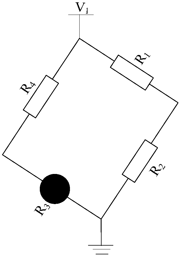
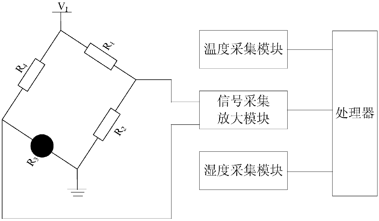
[0024] Such as figure 1 As shown, the improved catalytic combustion gas sensor in this embodiment includes a first resistor R 1 , the second resistor R 2 and black element R 3 , the first resistor R 1 The head of the terminal is connected to the supply voltage V 1 , the first resistor R 1 Connect the end of the second resistor R 2 The first end, the second resistor R 2 The end connects the black component R 3 One end and the second resistor R 2 As an improvement, the improved catalytic combustion gas sensor in this embodiment also includes a sampling element R 4 , the sampling element R 4 The head of the terminal is connected to the supply voltage V 1 , the sampling element R 4 The end connects the black component R 3 the other end; the sampling element R 4 The resistance is the black element R 3 Resistance of thermal resistance...


PUM


Abstract

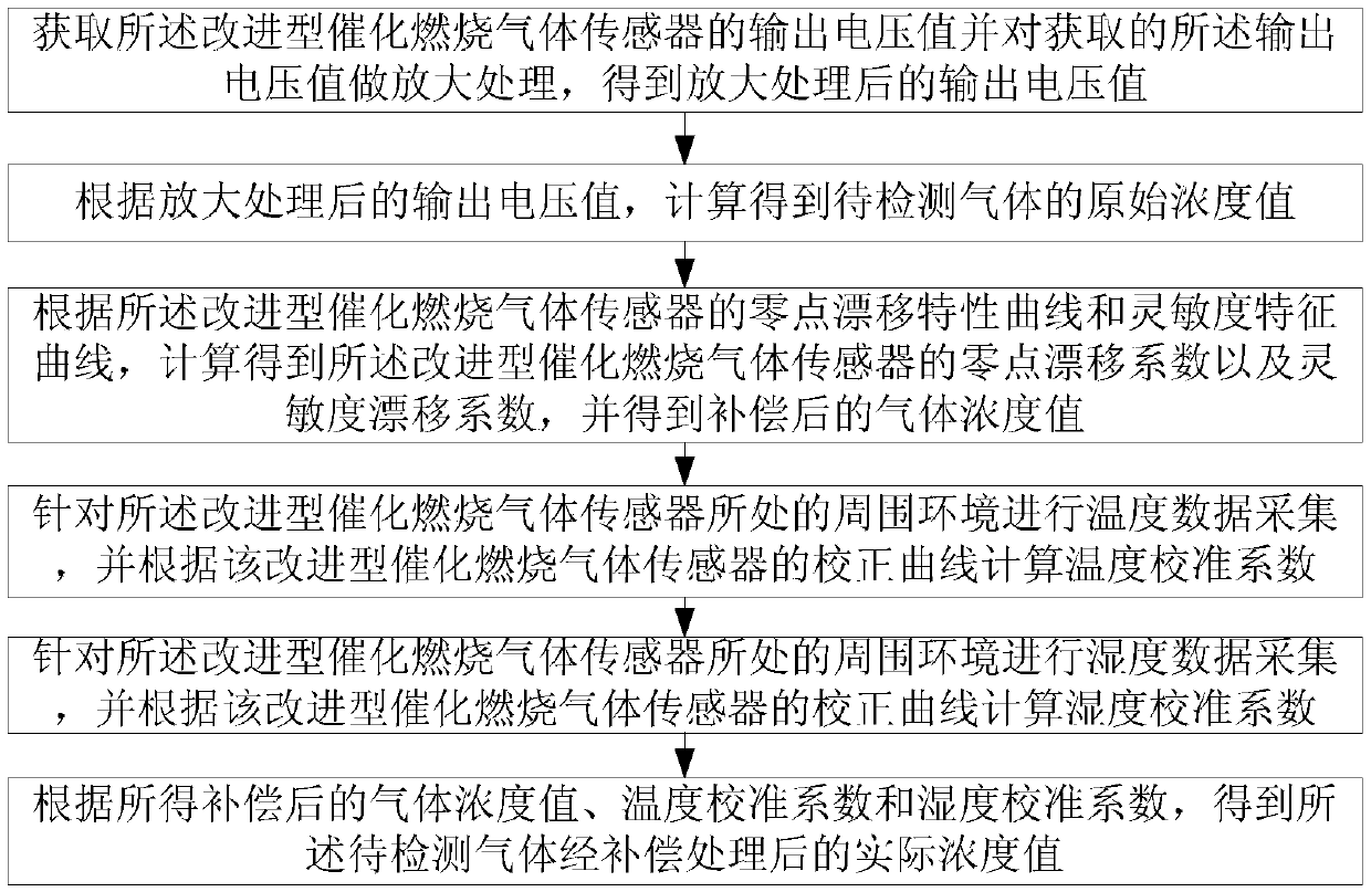
The invention relates to an improved catalytic combustion gas sensor and a gas detecting method. The catalytic combustion gas sensor comprises a first resistor, a second resistor and a black component. The head of the first resistor is connected to the power supply voltage. The tail end of the first resistor is connected to the head of the second resistor. The tail end of the second resistor is connected to one end of the black component and the tail end of the second resistor end is grounded. The catalytic combustion gas sensor is characterized in that the sensor comprises a sampling element,the head end of the sampling element is connected to the power supply voltage, the tail end of the sampling element is connected to the other end of the black component and the resistance of the sampling element is 1 / N times the thermal resistance of the black component, wherein N is greater than 1. Through acquiring a concentration of preliminary gas to be detected and a zero drift coefficient and a sensitivity drift coefficient of the gas sensor, a compensated gas concentration value is obtained, and through combination of a temperature calibration coefficient and a humidity calibration coefficient of the gas sensor, an actual concentration value of the compensated gas to be detected is obtained so that the adverse effects of temperature and humidity factors in the surrounding environment on the results detected by the gas sensor are reduced.

Description

technical field [0001] The invention relates to the field of gas detection, in particular to an improved catalytic combustion gas sensor and a gas detection method thereof. Background technique [0002] Catalytic combustion gas sensor is currently the most widely used detection device for detecting combustible gas. The traditional catalytic combustion gas sensor is a Wheatstone bridge composed of two sensor sensitive elements and two fixed resistors. The two sensor sensitive elements include black elements and white elements. When the mixed gas containing combustible gas and oxygen diffuses to the black element, it will burn quickly without flame and generate reaction heat, which will increase the resistance of the platinum wire resistance, and the bridge will output a changing voltage signal, which is consistent with the combustible gas It is directly proportional to the concentration of the white element and the black element, which have the same resistance value and perf...

Claims


Application Information

Patent Timeline
Patent Type & Authority Applications(China)
IPC IPC(8): G01N31/10G01N31/12
CPCG01N31/10G01N31/12
Inventor 蔡长青宋艳艳孙鸿涛张思祥李辉马晴天
Owner 北京惟泰安全设备有限公司
Learn More