Method of arranging structure health monitor sensors

A health monitoring and layout method technology, applied in the direction of instruments, special data processing applications, complex mathematical operations, etc., can solve the problems of complex calculation process, densely arranged sensors, not very suitable for health monitoring, etc., to achieve less consumption and better calculation process Simple and convenient operation

Inactive Publication Date: 2018-11-30
SHAOXING UNIVERSITY
View PDF4 Cites 2 Cited by
  • Summary
  • Abstract
  • Description
  • Claims
  • Application Information

AI Technical Summary

Problems solved by technology

However, due to the limitations of measuring equipment and cost, it is impossible to arrange sensors densely in structure, but only a few sensors, which inevitably involves the optimal arrangement of sensors
Although many sensor optimization layout methods have been proposed, such as the article "Study on Sensor Optimization Based on Multi-objective Genetic Algorithm" (Engineering Mechanics, 2007, 24(4), p168-172) published by Zhang Lianzhen et al. "Optimized Arrangement of Bridge Structure Sensors Based on Improved Genetic Algorithm" (Vibration and Shock, 2008, 27(3), p82-86) and "Optimized Arrangement of Cable-Stayed Bridge Sensors Based on EI and MAC Hybrid Algorithm" published by Yuan Aimin (Vibration, Testing and Diagnosis, 2009, 29(1), p55-59), but these methods are basically improved from related methods in the field of vibration control, not very suitable for health monitoring, and the calculation process is relatively complicated
In addition, under different constant loads, the layout of the sensors must be different. The current sensor layout methods do not consider the influence of the dead load.

Method used


Image

  • Method of arranging structure health monitor sensors
  • Method of arranging structure health monitor sensors
  • Method of arranging structure health monitor sensors

Examples


Embodiment Construction

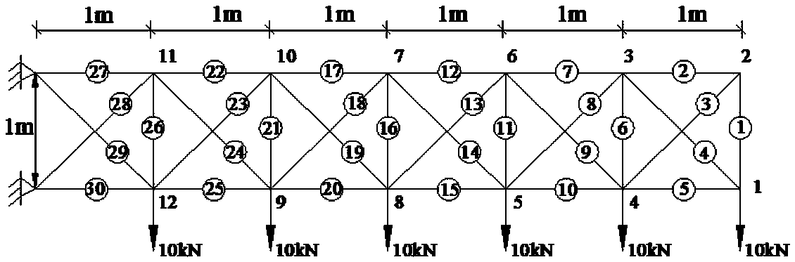
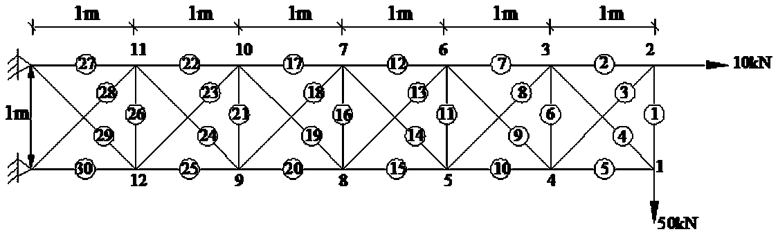
[0032] The following takes the same steel truss structure as the object to elaborate the technical scheme. The basic physical parameters of the selected steel truss structure are: elastic modulus E=200GPa, density ρ=7.8×10 3 kg / m 3 , the bar cross-sectional area A=7.85×10 -5 m.

[0033] External forces are mainly divided into two types: horizontal force and vertical force. For steel truss structures, the force can be divided into one-way force and two-way force. The following two types of one-way force and two-way force For the mode of action, analyze the transverse load action on the same steel truss respectively, see figure 1 with figure 2 , analyze the arrangement of sensors on it under the action of transverse load, which specifically includes the following steps:

[0034] (1) Establish a structural finite element model to obtain the structural stiffness matrix K;

[0035] (2) Decompose the stiffness matrix K, and decompose it into the product form of the degree of f...


PUM


Abstract

The application relates to a method of arranging structure health monitor sensors and belongs to the technical field of specific-field data processing methods. The method includes: establishing a structure finite element model to acquire a structure rigidity matrix, acquiring a structure flexibility matrix according to a reciprocal relation between the structure rigidity matrix and the structure flexibility matrix, supposing that members of a structure experience damage quantities of identical severity, and calculating flexibility changes corresponding to the members; sequentially calculatinga constant load vector that the structure bears and deformation energy changes corresponding to the members under the action of the constant load vector, sequentially calculating importance factors corresponding to the members, ranking the importance factors, and determining the key members; arranging sensors on the key members. When applied to structure health monitoring, the method features simple calculating process, low usage, good operation convenience and the like.

Description

technical field [0001] The present application relates to a method for arranging structural health monitoring sensors, and belongs to the technical field of data processing methods applicable to specific fields. Background technique [0002] During the service period of engineering structures, due to factors such as material aging, environmental corrosion, and external force collisions, the structure may be damaged. If the early damage of the structure cannot be monitored and repaired in time, it may cause serious loss of life and property (Yang Qiuwei, Liu Jike .Research Progress on Compliance Methods for Damage Identification of Engineering Structures. Vibration and Shock, 2011, 30(12):147-153). Therefore, it is necessary to use technical means to monitor the healthy working condition of the structure, so that maintenance and reinforcement can be carried out in time to avoid catastrophic consequences. [0003] At present, there are already many health monitoring or damage...

Claims


Application Information

Patent Timeline
IPC IPC(8): G06F17/50G06F17/16
CPCG06F17/16G06F30/23
Inventor 杨秋伟王伟李娜
Owner SHAOXING UNIVERSITY
Why Eureka
Try Eureka