Current transformer

A technology for current transformers and secondary windings, applied in the direction of inductors, transformers/inductor coils/windings/connections, circuits, etc., can solve the problem of large partial discharge of current transformers, reduce partial discharge, and reduce production cost, ease of implementation

Pending Publication Date: 2018-11-30
HENAN SENYUAN ELECTRIC CO LTD
View PDF11 Cites 0 Cited by
  • Summary
  • Abstract
  • Description
  • Claims
  • Application Information

AI Technical Summary

Problems solved by technology

[0005] The purpose of the present invention is to provide a current transformer to solve the problem of large partial discharge of the existing current transformer

Method used


Image

  • Current transformer
  • Current transformer
  • Current transformer

Examples


Embodiment Construction

[0024] The present invention will be further described below in conjunction with accompanying drawing.

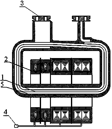
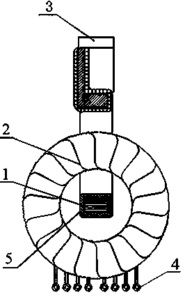
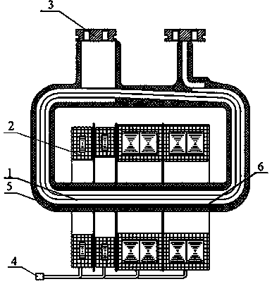
[0025] An embodiment of the current transformer of the present invention includes a cast insulator and a primary winding 1 and a secondary winding 2 sealed in the cast insulator, wherein the primary winding 1 and the secondary winding 2 are such as image 3 and Figure 4 As shown, the secondary winding 2 is circular, and the primary winding 1 is rectangular. The secondary winding 2 is sleeved on the lower side of the primary winding 1 and located on the winding path of the primary winding 1 . Among them, the primary winding 1 is wound by copper tape, and its cross-section is rectangular, and the two ends of the copper tape are connected with the primary terminal 3 ; the secondary winding 2 is connected with the secondary terminal 4 .

[0026] The upper and lower sides of the lower side of the primary winding 1 are provided with a spacer 6 respectively. The spacer 6 is a st...


PUM


Abstract

The invention relates to a current transformer. The current transformer comprises a pouring insulator, and a primary winding and a secondary winding which are fixed and encapsulated in the pouring insulator, wherein the secondary winding sleeves a winding path of the primary winding; a cushion block is supported on at least one side of a part, which is used for sleeving the secondary winding, of the first winding; the outer surface of the cushion block is arc-shaped. With the adoption of the technical scheme, the cushion block is arranged and a primary winding assembly can be prone to a roundshape; partial discharge is commonly caused by partial electric field centralization in an insulator or on the surface of the insulator, so that the partial discharge quantity of the current transformer can be effectively reduced when the primary winding assembly is prone to the round shape; a manner of setting the cushion block is adopted; the manner has a simple technology and stable quality andthe production cost can be reduced.

Description

technical field [0001] The present invention relates to current transformers. Background technique [0002] At present, with the continuous improvement of the State Grid's overall electrical equipment quality requirements, current transformers, as one of the main supporting electrical components, are facing a new challenge in improving product quality. In the entire product quality inspection project, partial discharge is a rigid indicator for judging product quality, especially when the rated voltage is 1.2Um, the national standard requires partial discharge to be ≤ 50pC, while the national grid requires partial discharge to be ≤ 20pC , far higher than the national standard, as a manufacturer, if there is no solid production technology as a basis, it is difficult to ensure that the quality of the products produced meets the requirements of the State Grid. [0003] A current transformer in the prior art such as Figure 1 to Figure 2 As shown, it includes a cast insulator (n...

Claims


Application Information

Patent Timeline
Patent Type & Authority Applications(China)
IPC IPC(8): H01F27/28H01F27/30H01F27/34H01F38/30
CPCH01F27/28H01F27/2847H01F27/306H01F27/34H01F38/30
Inventor 娄军峰刘军超谢群超王亚赛
Owner HENAN SENYUAN ELECTRIC CO LTD
Why Eureka
Try Eureka