Built-in permanent magnet motor

A permanent magnet motor, built-in technology, applied in the direction of magnetic circuits, electrical components, electromechanical devices, etc., can solve the problems of unspecified power density, etc., and achieve the effect of increased back EMF coefficient, high sine, and good linearity

Inactive Publication Date: 2018-11-30
GUANGDONG WELLING ELECTRIC MACHINE MFG
View PDF2 Cites 8 Cited by
  • Summary
  • Abstract
  • Description
  • Claims
  • Application Information

AI Technical Summary

Problems solved by technology

However, the above-mentioned patents only rely on parameters such as stator slot width, tooth width, and yoke width to average the flux density, and fail to consider the influence of the stator shape and structure on the motor magnetic field and loss, etc., and are not suitable for high power density motor structures. , also in order to reduce the vibration and noise of the motor through the combination method between the stator core and the casing, no structure that can comprehensively consider the power density and suppress vibration and noise

Method used


Image

  • Built-in permanent magnet motor
  • Built-in permanent magnet motor
  • Built-in permanent magnet motor

Examples


Embodiment Construction

[0070] Specific embodiments of the present invention will be described in detail below in conjunction with the accompanying drawings. It should be understood that the specific embodiments described here are only used to illustrate and explain the present invention, and are not intended to limit the present invention.

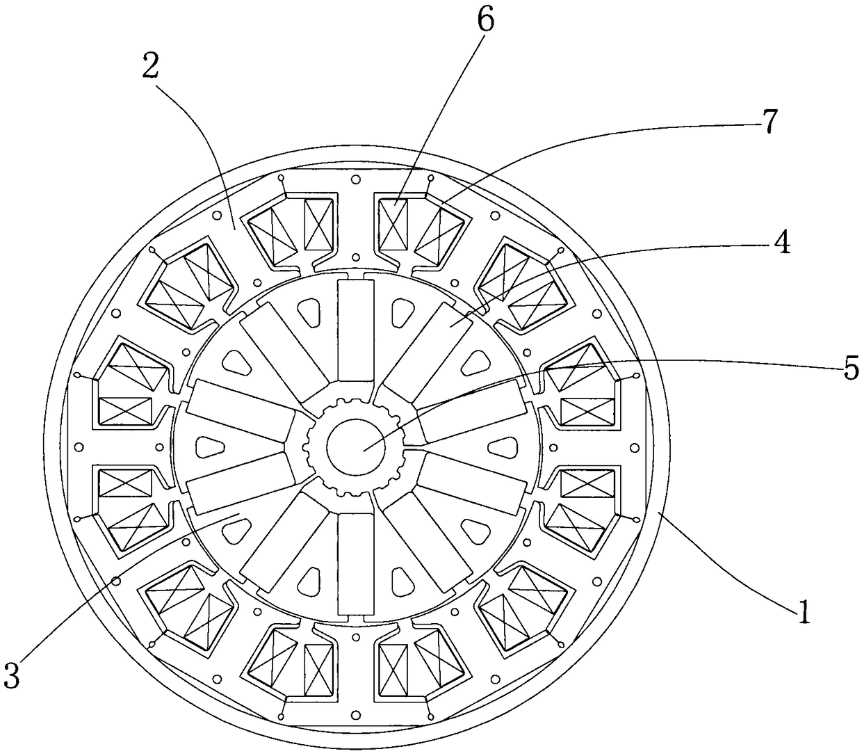
[0071] Such as figure 1 As shown, an embodiment of the present invention is a permanent magnet brushless DC motor, including a casing 1, a regular polygonal stator core 2, an asymmetric hybrid stacked rotor core 3, a permanent magnet 4, a shaft 5, a winding 6 and an insulation Framework 7.

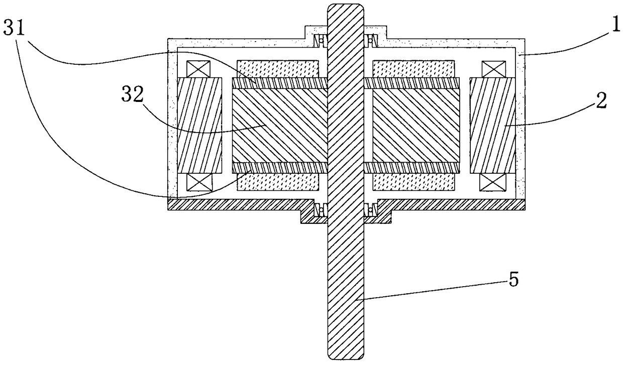
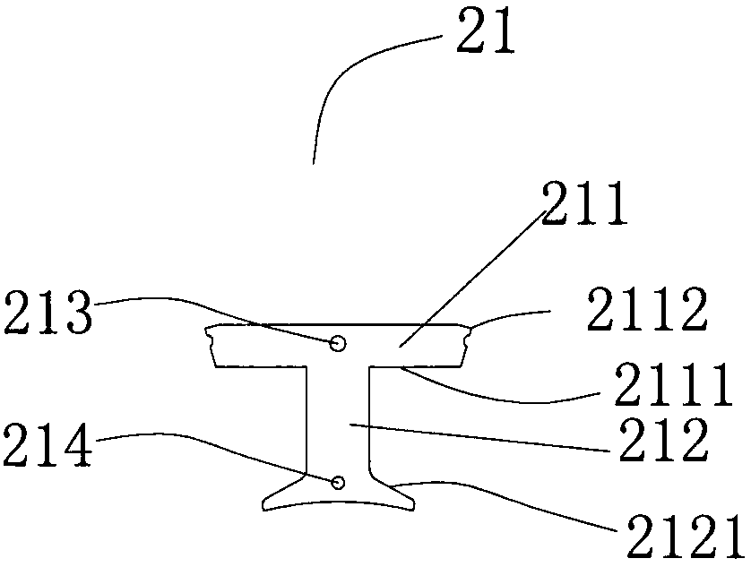
[0072] Such as image 3 and 4 As shown, the stator core 2 is surrounded by 12 T-shaped tooth yokes 21, and the stator core 2 and the casing 1 are in contact through the connection points between adjacent T-shaped tooth yokes 21, and the contact parts form The contact area 22, the outer surface or top surface of the yoke portion 211 of each T-shaped toothed yoke 21 is a p...


PUM


Abstract

The invention relates to the field of permanent magnet motors, and discloses a built-in permanent magnet motor. The built-in permanent magnet motor comprises a case, a regular polygonal stator iron core, an asymmetric hybrid rotor iron core, permanent magnets, a shaft, windings and insulating frames. The regular polygonal stator iron core is defined by a plurality of T-shaped tooth connection yokes. The contact part of the regular polygonal stator iron core and the case forms a contact area, and a gap between the regular polygonal stator iron core and the case forms a filling area. The asymmetric hybrid rotor iron core comprises a shaft sleeve, a shaft hole, a fan area, connecting bridges and supporting protrusions and contains full-connecting-bridge-type laminations and a half-connecting-bridge-type lamination. The full-connecting-bridge-type laminations are located at the two ends of the asymmetric hybrid rotor iron core, and the half-connecting-bridge-type lamination is clamped by the full-connecting-bridge-type laminations in a wrapped mode in the axial direction. Tooth parts of all the T-shaped tooth connection yokes are wrapped with the insulating frames. The windings are wound around the insulating frames. According to the built-in permanent magnet motor, the production technology of the motor can be simplified, and the structural strength of the motor can also be improved.

Description

technical field [0001] The invention relates to the field of permanent magnet motors, in particular to a built-in permanent magnet motor. Background technique [0002] Traditional brushless DC motors use surface-mounted magnetic tiles or built-in radially magnetized magnet steel structures, which have low power density and are limited by cost factors. The magnetic flux per pole of the motor is increased by tangentially magnetized parallel magnetic circuit structures. The existing tangential magnetization structure still has the problem of large flux leakage, which limits the performance improvement of the motor. [0003] Patent CN201611226568.0 designs a rotor core, which has at least one tooth sector disconnected from the rotor collar, and at least one tooth sector connected to the shaft sleeve. This suppresses magnetic flux leakage near the axis. The rotor iron core shaft sleeve is provided with a positioning protrusion for positioning and supporting the permanent magnet...

Claims


Application Information

Patent Timeline
Patent Type & Authority Applications(China)
IPC IPC(8): H02K1/28H02K1/27
CPCH02K1/2706H02K1/28H02K2201/06H02K2213/03
Inventor 李文瑞甘峰李虎迟闯于明湖
Owner GUANGDONG WELLING ELECTRIC MACHINE MFG
Why Eureka
Try Eureka