Ultrasonic material distribution structure

A technology of ultrasonic wave and material distribution plate, which is applied in the direction of solid separation, filter screen, grid, etc., and can solve the problems of large influence, no separation or passage, and low efficiency

Inactive Publication Date: 2018-12-04
广东仁开科技有限公司
View PDF13 Cites 1 Cited by
  • Summary
  • Abstract
  • Description
  • Claims
  • Application Information

AI Technical Summary

Problems solved by technology

[0002] Ultrafine powder is usually divided into micron-scale, sub-micron-scale and nano-scale powders, which can be prepared by chemical and physical methods, but no matter what kind of ultrafine powder is prepared, the fine particles tend to aggregate together to form Agglomerated particles, this spontaneous aggregation tendency will have an adverse effect on the process and performance of ultrafine powders, especially metal ultrafine powders, the particles themselves have a certain charge, and the bonding force of agglomeration is stronger and the impact is greater
[0003] After the metal ultrafine powder is prepared, it is usually sieved by an ultrasonic vibrating sieve to separate particles with various particle size distributions, remove agglomerated particles with strong binding force and other impurities, and obtain metal ultrafine powder with uniform particle size , but whether it is sieved in the form of ultrasonic circular vibrating sieve or linear sieve, it is directly fed from the top of the equipment to the screen without any feeding treatment, resulting in some agglomerated particles with weak binding force still agglomerated in the sieve. One piece does not separate or pass through the screen holes when the screen vibrates, but is sieved out as non-passing objects, and the non-passing objects are physically crushed and then sieved again. This method requires repeated operations, increases the process, and improves efficiency. Low, so the feed treatment should be done before sieving the freshly prepared metal ultrafine powder to disperse the particles

Method used


Image

  • Ultrasonic material distribution structure
  • Ultrasonic material distribution structure

Examples


Embodiment Construction

[0014] In order to further understand the inventive content, characteristics and effects of the present invention, the following examples are hereby described.

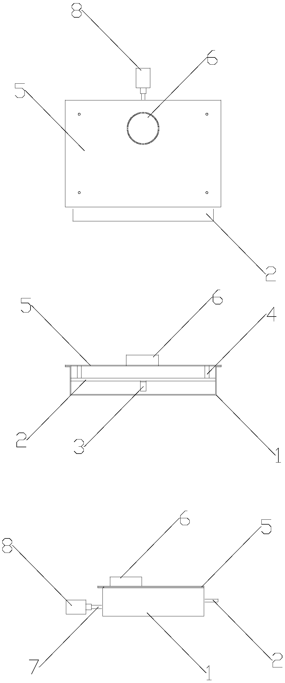
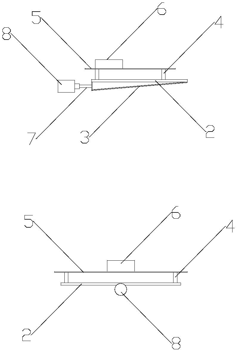
[0015] see Figure 1-2 , the technical scheme adopted in the present invention is as follows: an ultrasonic material distribution structure, which consists of a casing 1, a material distribution plate 2, a transmission plate 3, a connecting column 4, a fixed plate 5, a feeding port 6, a transmission rod 7, an ultrasonic transducer 8, the casing 1 is in the shape of a cuboid, its upper surface and one side are set as openings, the fixing plate 5 is arranged on the upper surface of the casing 1, the fixing plate 5 and the periphery of the casing 1 are fixedly connected by welding, and the feeding port 6 is cylindrical. The cavity is arranged on the upper surface of the fixing plate 5 and penetrates through the fixing plate 5. The distribution plate 2 is arranged in the middle of the inner cavity of the casing 1 and exte...


PUM


Abstract

The invention discloses an ultrasonic material distribution structure. The structure is composed of a shell, a material distribution plate, a transmission plate, connecting columns, a fixing plate, afeeding port, a transmission rod and an ultrasonic transducer, and an original feeding mode of screening equipment is replaced. According to the structure, through the high-frequency vibration of theultrasonic transducer, the material distribution plate is vibrated, the amplitude on the powder body at each position of the material distribution plate is different, so that the powder body is stressed unevenly, the binding force of agglomeration particles is destroyed, the agglomeration particles are out of balance, the powder is dispersed to the periphery, so that the effect of particle dispersion is achieved; and the material distribution plate is inclined downwards by a certain angle, the powder particles can fall out dispersedly under the amplitude motion force of the material distribution plate and the self-gravity, so that the powder is screened more sufficiently by subsequent screen meshes, and repetitive screening procedures are reduced.

Description

technical field [0001] The invention belongs to the technical field of vibrating screen equipment, and in particular relates to an ultrasonic material distribution structure. Background technique [0002] Ultrafine powders are usually divided into micron, submicron and nanoscale powders, which can be prepared by chemical and physical methods, but no matter which method of ultrafine powder is prepared, the fine particles tend to aggregate together and form Agglomerated particles, this spontaneous aggregation tendency will adversely affect the process and performance of ultra-fine powder, especially metal ultra-fine powder, the particles themselves have a certain charge, and the binding force of agglomeration is stronger and the impact is greater. . [0003] After the metal ultrafine powder is prepared, it is usually sieved by an ultrasonic vibrating sieve to sieve particles of various particle size distributions, remove the agglomerated particles with strong binding force an...

Claims


Application Information

Patent Timeline
Patent Type & Authority Applications(China)
IPC IPC(8): B07B1/46
CPCB07B1/46B07B2230/04
Inventor 陈庆仁欧阳厚生车洪斌
Owner 广东仁开科技有限公司
Why Eureka
Try Eureka