Cutting device and method for fiber web winding machine

A technology of cutting device and fiber web, which is applied in the direction of winding mechanism, winding strip, fiber processing, etc., can solve the problem of unreliable arrival of fiber web to the winding shaft, etc., and achieve the effect of simple structure and no waste of operating energy

Active Publication Date: 2020-10-02
TRUETZSCHLER GRP SE
View PDF18 Cites 0 Cited by
  • Summary
  • Abstract
  • Description
  • Claims
  • Application Information

AI Technical Summary

Problems solved by technology

However, in both separating device variants, there is the problem that the cut web does not reach the empty, new winding shaft to be wound up reliably, where the web adheres to sticky surfaces, The surface is realized, for example, with an adhesive layer

Method used


Image

  • Cutting device and method for fiber web winding machine
  • Cutting device and method for fiber web winding machine
  • Cutting device and method for fiber web winding machine

Examples


Embodiment Construction

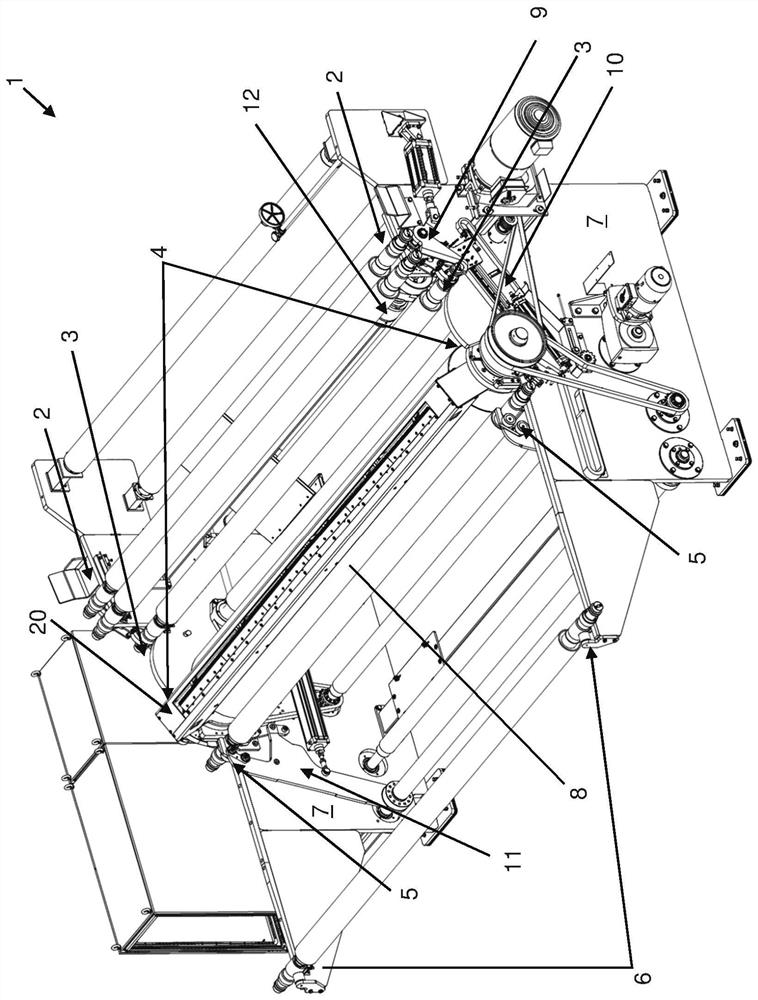
[0028] figure 1 A web winding machine 1 according to an embodiment of the invention is shown. Components that are not essential to the invention will not be explained further.

[0029] The web winding machine 1 essentially comprises two frame walls 7 , which form a frame by means of connecting bodies, not shown, which accommodate or hold all other functional components of the web winding machine 1 .

[0030] On the right, the machine frame wall 7 has a depository 2 in which not shown (here: two) winding shafts are located.

[0031]The web winder 1 also comprises a recess on each frame wall 7 which defines a waiting position 3 for the winding shaft. Since the winding shaft is held on both sides by the respective frame wall 7 , the waiting position 3 is realized with two frame walls 7 .

[0032] In the waiting position 3 , the winding shaft arranged in the waiting position is set into rotation by means of the starting section 12 . Here, the start-up section 12 contacts the l...


PUM


Abstract

A device, incorporated into a web winding machine (1), such that the web is separated at a given position during winding onto the winding shaft such that the free end resulting from the separation points in the direction of the portion of the web in the direction of transport of the web Conveying on winding shafts arranged against the conveying direction. Also disclosed is a web winding machine with the above-mentioned device and a drive that brings the above-mentioned device from a waiting position to an operating position and then winds the web with a contact roller (8) on a first winding shaft. There is also a pressure element, which makes the first winding shaft press against the contact roller, so that the fiber web to be wound is wound on the first winding shaft due to friction, and the fiber web is separated by this device and part of the fiber web is moved to the second winding shaft. Winding shaft delivery. Also relates to a method of operating a web winder: winding an incoming web around a first winding shaft; separating the web if a separation state (S2) is detected, and upon completion of the separation of the web or immediately thereafter Finally, a part of the web is conveyed in the direction of the second winding axis.

Description

technical field [0001] The invention relates to a cutting device for a web winding machine, a web winding machine equipped with such a device and a method for a web winding machine equipped with such a device. Background technique [0002] Fiber web winders are known. They are used for winding fiber webs, for example from cards, onto winding shafts. For this purpose, an empty winding bobbin is inserted into the depository of the web winding machine and first brought to the waiting position shortly thereafter. The waiting position serves, on the one hand, to separate the winding shaft from the other winding shafts and, on the other hand, to set it in rotation when the actual winding process begins. [0003] In order to end the winding of a winding shaft and start the winding of a subsequent, empty winding shaft, it is necessary to separate the fiber web. For this purpose, it is known to move a rotating cutter transverse to the axis of rotation of a contact roll of a web wi...

Claims


Application Information

Patent Timeline
Patent Type & Authority Patents(China)
IPC IPC(8): B65H19/26D06H7/00D01G27/00D01G21/00
CPCB65H19/26D01G21/00D01G27/00D06H7/00B65H19/28B65H2301/41425B65H2701/177
Inventor 菲利普·绪特安德烈亚斯·哈赫曼安德烈亚斯·胡宾格
Owner TRUETZSCHLER GRP SE
Why Eureka
Try Eureka