Motor test bench of new energy automobile

A new energy vehicle, motor testing technology, applied in motor generator testing, measuring devices, force/torque/work measuring instruments, etc., can solve the problem of being easily affected by gravity factors, multi-time, insufficient installation and removal of the motor under test convenience, etc.

Active Publication Date: 2018-12-04
HUNAN MECHANICAL & ELECTRICAL POLYTECHNIC
View PDF6 Cites 7 Cited by
  • Summary
  • Abstract
  • Description
  • Claims
  • Application Information

AI Technical Summary

Problems solved by technology

The output shaft of the existing motor under test is connected to the transmission shaft on the test bench using a coupling, and it takes a lot of time to install the coupling, and the keyway on the output shaft of the motor under test of different types The sizes are different, and it is difficult for each test bench to be suitable for installing a variety of different types of motors under test for testing. The installation and disassembly of the motor under test on the test bench is not convenient enough, and the motor under test 13 and the transmission components on the traditional test bench are both Horizontal setting, this setting method makes the test structure of the test bench vulnerable to the influence of gravity, and the test results are not accurate enough

Method used


Image

  • Motor test bench of new energy automobile
  • Motor test bench of new energy automobile

Examples


Embodiment Construction

[0015] In order to make the purpose, technical solutions and advantages of the embodiments of the present invention clearer, the technical solutions in the embodiments of the present invention will be clearly and completely described below in conjunction with the drawings in the embodiments of the present invention. Obviously, the described embodiments It is a part of embodiments of the present invention, but not all embodiments. Based on the embodiments of the present invention, all other embodiments obtained by persons of ordinary skill in the art without creative efforts fall within the protection scope of the present invention.

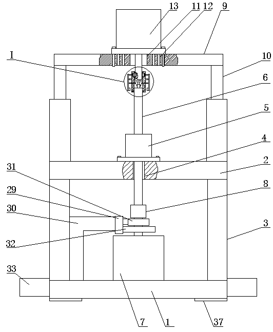
[0016]The new energy vehicle motor test bench, as shown in the figure, includes a base 1. The upper part of the base 1 is provided with a horizontal mounting plate 2. The bottom of the mounting plate 2 near the four corners is fixedly connected with the upper part of the base 1 through a column 3. The first through hole 4 is provided in the middle...


PUM


Abstract

The invention relates to a motor test bench of a new energy automobile. The motor test bench comprises a pedestal; and a lateral mounting plate is arranged at the upper part of the pedestal. The parts, near the four corners, of the bottom of the mounting plate are fixedly connected with the upper part of the pedestal by standing posts. A first through hole is formed in the middle of the top of themounting plate. A vertical bearing base is fixedly installed in the middle of the top surface of the mounting plate; and a vertical transmission shaft is installed in the bearing base movably througha bearing. A vertical high-speed dynamometer motor is fixedly installed in the middle of the upper part of the pedestal; and the upper end of a rotating shaft of the high-speed dynamometer motor andthe lower end of the transmission shaft are connected by a double-diaphragm coupler. On the basis of cooperation of an output shaft and a vertical tube, connection between a tested motor output shaftand the transmission shaft is carried out quickly; and a pin key is drawn out of a key slot when the lower end of a lever is pressed, so that the tested motor output shaft is separated from the vertical tube conveniently based on the design. Therefore, the tested motor is mounted or dismounted conveniently; the mounted and dismounted processes are simplified; the test efficiency is improved effectively; and the labor intensity of the staff is reduced.

Description

technical field [0001] The invention belongs to the technical field of motor test equipment, in particular to a new energy vehicle motor test bench. Background technique [0002] With the continuous development of the automobile industry, the new energy automobile industry with energy saving and environmental protection as the development direction has received more and more attention. The requirements for new energy motors are getting higher and higher, and the corresponding testing standards are also constantly improving. New energy motor test bench is a special testing equipment for factory test and type test of new energy motors, permanent magnet synchronous motors or asynchronous motors installed on pure electric vehicles or hybrid vehicles and driven by special controllers. Bad directly affects the reliability and practicability of the test results. In the existing technology, the structure of the motor test bench can only be used for testing ordinary motors and gener...

Claims


Application Information

Patent Timeline
Patent Type & Authority Applications(China)
IPC IPC(8): G01R31/34G01L5/00
CPCG01L5/00G01R31/34
Inventor 曹晓娟张如义
Owner HUNAN MECHANICAL & ELECTRICAL POLYTECHNIC
Why Eureka
Try Eureka