Supercharge Your Innovation With Domain-Expert AI Agents!

Phase correction circuit and phase correction method

A phase correction and circuit technology, applied in the direction of instruments, computer control, simulators, etc., can solve the problem that it cannot be fixed at 90 degrees

Active Publication Date: 2018-12-04
RDC SEMICON CO LTD
View PDF6 Cites 0 Cited by
  • Summary
  • Abstract
  • Description
  • Claims
  • Application Information

AI Technical Summary

Problems solved by technology

However, due to temperature or environmental factors during the photoelectric conversion process, the phase difference between the two photoelectric signals A1, B1 may not be fixed at 90 degrees

Method used


Image

  • Phase correction circuit and phase correction method
  • Phase correction circuit and phase correction method
  • Phase correction circuit and phase correction method

Examples


Embodiment Construction

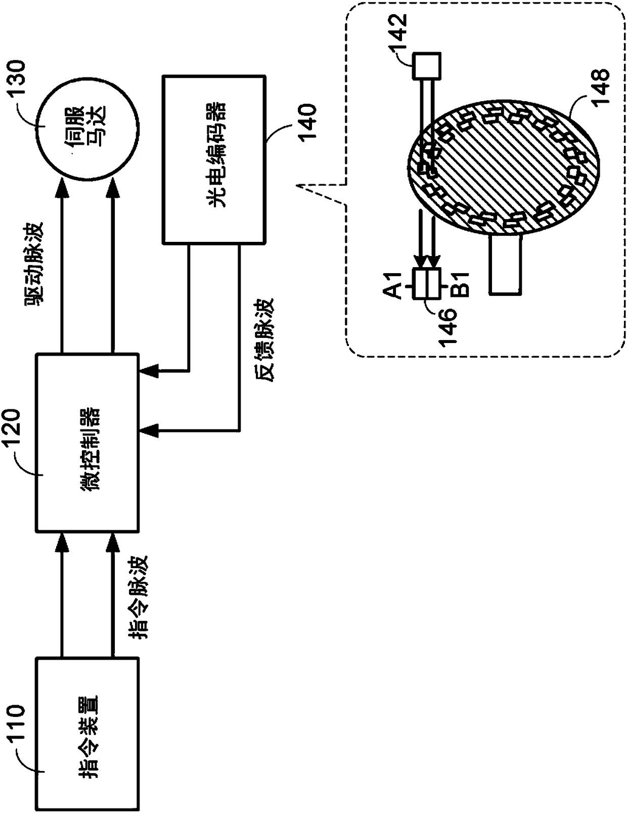
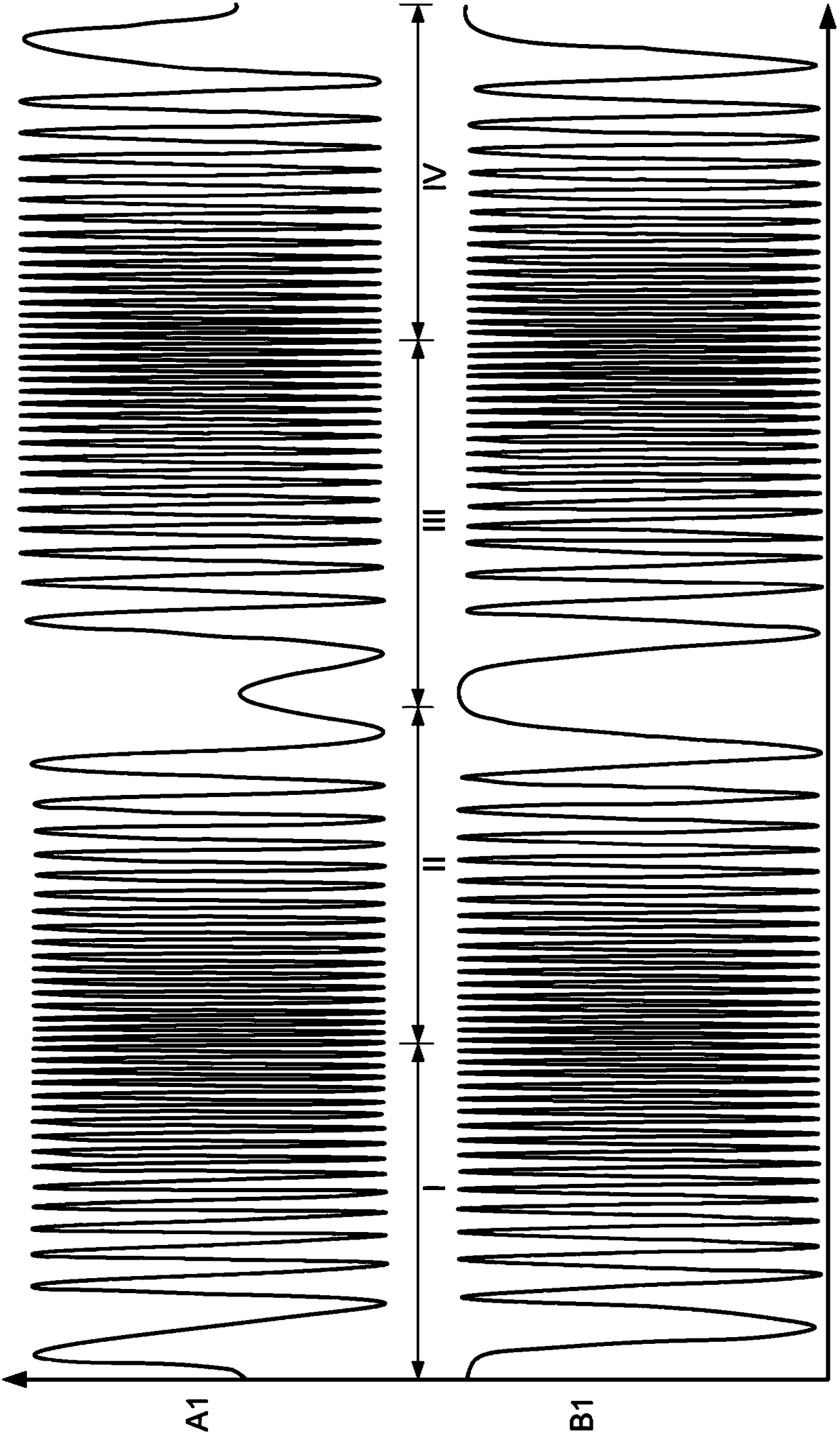
[0037] The present invention proposes a phase correction circuit and a phase correction method for correcting two photoelectric signals A1 and B1 generated by a photodetector in a servo motor system. The phase difference between the corrected two corrected signals Ac and Bc is 90 degrees.

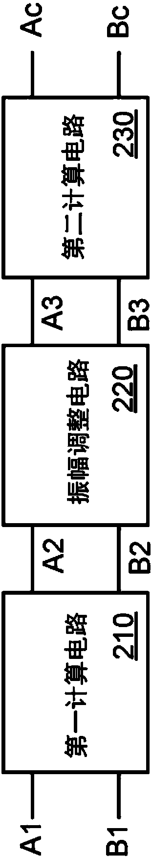
[0038] Please refer to figure 2 , which is a schematic diagram of the phase correction circuit of the present invention. The phase correction circuit 100 includes a first calculation circuit 110 , an amplitude adjustment circuit 120 , and a second calculation circuit 130 .

[0039] Wherein, the first calculation circuit 210 receives the two photoelectric signals A1 and B1 generated by the photodetector, and generates conversion signals A2 and B2. The amplitude adjustment circuit 220 receives the two conversion signals A2, B2, adjusts the two conversion signals A2, B2 into adjustment signals A3, B3 having the same amplitude, and outputs the two adjustment signals A3, B3. The second calcu...


PUM


Abstract

The present invention is a phase correction circuit and a phase correction method, wherein the phase correction circuit includes: a first calculation circuit used for receiving a first photoelectric signal and a second photoelectric signal and generating a first conversion signal and a second a conversion signal, an amplitude adjustment circuit used for receiving the first conversion signal and the second conversion signal and generating a first adjustment signal and a second adjustment signal, and a second calculation circuit used for receiving the first adjustment signal and the second adjustment signal and generating a first correction signal and a second correction signal. The phase difference between the first correction signal and the second correction signal is 90 degrees.

Description

technical field [0001] The present invention relates to a signal processing device and processing method, and in particular to a phase correction circuit and a phase correction method in a servomotor system. Background technique [0002] As we all know, the servo motor system can accurately control the rotation speed of the servo motor, and has the ability to accelerate, decelerate, and reverse quickly. That is, since the servo motor system has the capability of precise position control and speed control, it has been widely used in various automation industries and precision machining fields. For example, a robotic arm, or a mechanical working platform, etc. [0003] Please refer to Figure 1A , which shows a schematic diagram of the servo motor system. The servo motor system includes: a command device 110 , a micro controller (micro controller) 120 , a servo motor 130 , and an optical encoder (optical encoder) 140 . [0004] The command device 110 outputs command pulses ...

Claims


Application Information

Patent Timeline
Patent Type & Authority Applications(China)
IPC IPC(8): G05B19/042
CPCG05B19/0423G05B2219/21126
Inventor 尤信雄
Owner RDC SEMICON CO LTD
Features
  • R&D
  • Intellectual Property
  • Life Sciences
  • Materials
  • Tech Scout
  • Unparalleled Data Quality
  • Higher Quality Content
  • 60% Fewer Hallucinations
Learn More