Crop straw crusher

A technology of crop straw and pulverizer, which is applied in the field of straw pulverization, can solve the problems of dead corners and uneven thickness of crushed powder, and achieve the effect of good cutting effect, reducing dead corners and thorough cutting.

Active Publication Date: 2018-12-07
沈军
View PDF4 Cites 3 Cited by
  • Summary
  • Abstract
  • Description
  • Claims
  • Application Information

AI Technical Summary

Problems solved by technology

[0004] The purpose of the present invention is to solve the problem that there is a dead angle in the pulverizing process of the pulverizer in the prior art, which leads to the problem of uneven thickness of the crushed powder after straw pulverization, and proposes a crop straw pulverizer

Method used


Image

  • Crop straw crusher
  • Crop straw crusher
  • Crop straw crusher

Examples


Embodiment 1

[0029] In describing the present invention, it should be understood that the terms "upper", "lower", "front", "rear", "left", "right", "top", "bottom", "inner", " The orientation or positional relationship indicated by "outside", etc. is based on the orientation or positional relationship shown in the drawings, and is only for the convenience of describing the present invention and simplifying the description, rather than indicating or implying that the referred device or element must have a specific orientation, so as to specific orientation configuration and operation, and therefore should not be construed as limiting the invention

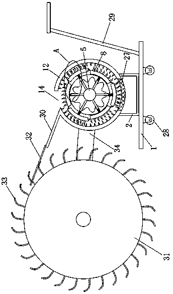
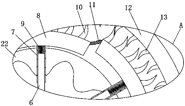
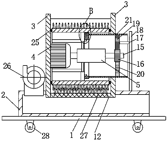
[0030] refer to Figure 1-5 , a crop straw grinder, comprising a bottom plate 1, a crushing bin 2 is welded on the bottom plate 1, two side plates 3 are welded on the upper end of the crushing bin 2, and a motor 4 is installed on the side plate 3 on the left side using bolts, The output shaft of the motor 4 is welded with a center wheel 5, and ...

Embodiment 2

[0039] The difference between Embodiment 2 and Embodiment 1 is that: the left end of the crushing bin 2 is equipped with a fan 26 using bolts, the air inlet end of the fan 26 communicates with the outside world, and the blowing end of the fan 26 is connected to the inside of the crushing bin 2. The right wall of the warehouse 2 is open. When the device is placed in the field, the fan 26 can directly blow the crushed stalks to the field, and return them to the field without manual handling of the crushed stalks. .

Embodiment 3

[0041] The difference between the third embodiment and the second embodiment is that four rollers 28 are symmetrically welded on the bottom surface of the bottom plate 1, and a push handle 29 is welded on the bottom plate 1, which is convenient for the user to push the device in the field. Both side plates 3 are welded There is a connecting plate 34, and the two connecting plates 34 are jointly connected with a pin shaft to rotate and connect with a material receiving barrel 31, and the outer wall of the material receiving barrel 31 is evenly welded with a plurality of thin claws 33, and the edge of the feeding port 14 is welded with a material guide plate 30, A plurality of steel wires 32 are welded on the material guide plate 30. When there are many straws scattered in the field, there is no need to manually store the straws into the feeding port 14. The user only needs to push the device until the straws are scattered. At this time, the receiving barrel 31 rolls along the gr...


PUM


Abstract

The invention discloses a crop straw crusher. The crusher comprises a bottom plate, a powder bin is welded to the bottom plate, and two side plates are welded to the upper end of the powder bin; a motor is installed on the left side plate through bolts, and a center wheel is welded to an output shaft of the motor. The crusher has the advantages that the motor drives arc-shaped plates to rotate soas to drive a first blade to rotate, so that two blades complete cutting of straw together; a sliding sleeve slides along the inner wall track of a flower-shaped guide rail, and then each arc-shaped plate slides back and forth in the direction of a sliding column so that the first blade can slide and cut in the direction of the sliding column while rotating and cutting; the flower-shaped guide rail is driven by a gear ring part structure to rotate, so that the movement track of the first blade is more complex; it is guaranteed that in the running process of the device, when the two blades areused for cutting the straw, the straw can be thoroughly cut and crushed without generating cutting dead corners.

Description

technical field [0001] The invention relates to the technical field of straw crushing, in particular to a crop straw crushing machine. Background technique [0002] When harvesting herbaceous plants such as soybeans and gramineous plants such as wheat and rice every year, a lot of straws are often produced. However, the recycling rate of these straws is extremely low, and most of them are only used as biofuels, which not only causes great material waste, It also pollutes a lot of air. [0003] Straw contains a lot of energy, which can not only be used for animal husbandry after being crushed, but also can be returned to the field on the spot. However, the crushing effect of the existing pulverizers is poor, and there is a situation of crushing dead angles, resulting in uneven thickness of crushed straw after crushing. Contents of the invention [0004] The purpose of the present invention is to solve the problem that there are dead angles in the pulverizing process of th...

Claims


Application Information

Patent Timeline
Patent Type & Authority Applications(China)
IPC IPC(8): A01D82/00
CPCA01D82/00
Inventor 姜丽明
Owner 沈军
Why Eureka
Try Eureka