An in-situ visualization system for X-ray fluoroscopic imaging and its calibration method

An X-ray, in-situ technology, applied in the field of in-situ visualization systems of X-ray fluoroscopic imaging, can solve problems such as hand-eye incongruity

Active Publication Date: 2020-10-23
TSINGHUA UNIV
View PDF13 Cites 0 Cited by
  • Summary
  • Abstract
  • Description
  • Claims
  • Application Information

AI Technical Summary

Problems solved by technology

However, during the operation, in addition to the information of the entry point of the operation, the doctor also needs to observe the relevant anatomical structure, which still needs to be obtained from the screen, and there is still the problem of hand-eye incoordination

Method used


Image

  • An in-situ visualization system for X-ray fluoroscopic imaging and its calibration method
  • An in-situ visualization system for X-ray fluoroscopic imaging and its calibration method
  • An in-situ visualization system for X-ray fluoroscopic imaging and its calibration method

Examples


Embodiment Construction

[0047] The present invention will be further elaborated below through specific embodiments in conjunction with the accompanying drawings.

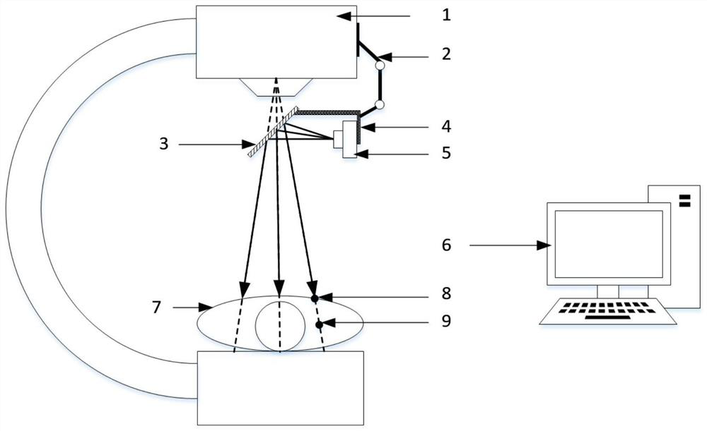
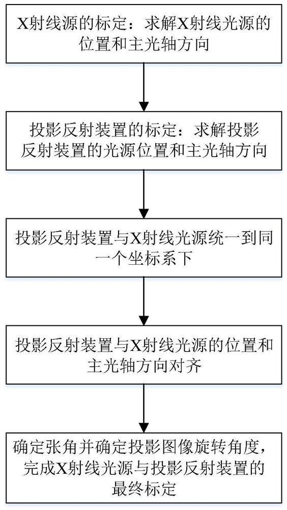
[0048] Such as figure 1 As shown, the in-situ visualization system of X-ray fluoroscopy imaging in this embodiment includes: X-ray imaging system 1, projection reflection device, adjustment device 2, computer 6 and calibration tool; wherein, X-ray imaging system includes X-ray source and detection One end of the adjustment device 2 is fixed on the housing of the X-ray source, and the other end is connected to the projection reflection device; the projection reflection device includes a mirror 3, a projector 5 and a connecting piece 4, and one end of the connecting piece 4 is fixed to the reflecting mirror 3, and the other end The projector 5 is fixed; the X-ray imaging system 1 is connected to the computer 6 through a network cable; the projector 5 is connected to the computer 6 through a data cable. The optical path of the projection ref...


PUM


Abstract

The invention discloses an in-situ visualization system of X-ray fluoroscopy imaging and a calibration method thereof. By adopting the in-situ visualization system of X-ray fluoroscopy imaging and thecalibration method thereof, an acquired fluoroscopy image is projected on the surface of an imaging object according to an original X-ray path; an operator can acquire internal image information of the object simply by viewing fluoroscopy image projection on the surface of the object. According to the in-situ visualization system of X-ray fluoroscopy imaging and the calibration method thereof, acalibration device and a first optical tracking system tool are adopted to determine the position and main optical axis of an X-ray source, then, a second optical tracking system tool, a third opticaltracking system tool and a spatial position pick-up tool are adopted to determine the position and main optical axis of a projection reflection device, after the position and main optical axis of theX-ray source and the position and main optical axis of the projection reflection device are uniformly converted to the same coordinate system, aligning is conducted, the projection field angles are further unified, image directions are aligned, and therefore the calibration of the X-ray source and the calibration of the projection reflection device can be conveniently completed.

Description

technical field [0001] The invention relates to the technical field of medical devices, in particular to an in-situ visualization system for X-ray perspective imaging and a calibration method thereof. Background technique [0002] The mobile C-arm X-ray machine is a commonly used imaging device in clinical practice, and plays an important role in the diagnosis, positioning and navigation of minimally invasive orthopedics and other operations. However, in actual surgery, it is necessary to use X-ray fluoroscopy imaging to observe the real-time position of the operating tool relative to the lesion point, and its viewing angle needs to be repeatedly switched between the operating part and the image display device, which is not conducive to hand-eye coordination. At the same time, the above process requires repeated fluoroscopy, which will bring more ionizing radiation to doctors. [0003] In order to solve the above problems, the patent issued by the United States (US 7198404B...

Claims


Application Information

Patent Timeline
Patent Type & Authority Patents(China)
IPC IPC(8): A61B6/00
CPCA61B6/44A61B6/54A61B6/58
Inventor 王广志梁利斌邢树伟丁辉
Owner TSINGHUA UNIV
Why Eureka
Try Eureka