Dispersion equipment for coating production

A dispersing and coating technology, applied in the directions of dissolving, mixing machines, chemical instruments and methods, etc., can solve the problems of raw material waste, poor coating dispersion quality, low work efficiency, etc., to improve quality, improve dispersion efficiency and dispersion quality, The effect of reducing waste

Inactive Publication Date: 2018-12-07
周兆平
View PDF6 Cites 2 Cited by
  • Summary
  • Abstract
  • Description
  • Claims
  • Application Information

AI Technical Summary

Problems solved by technology

[0003] The purpose of the present invention is to solve the problems of unsatisfactory paint dispersing effect, inability to disperse paint at different depths and angles, low work efficiency, more waste of raw materials, and poor paint dispersion quality existing in the existing paint dispersing machine. Provide a dispersing equipment suitable for the production of coatings with reasonable structure design, convenient operation, high work efficiency, the ability to disperse coatings at different depths and angles, good dispersion effect of coatings, and less waste of raw materials

Method used


Image

  • Dispersion equipment for coating production
  • Dispersion equipment for coating production
  • Dispersion equipment for coating production

Examples


Embodiment 1

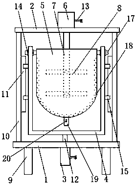
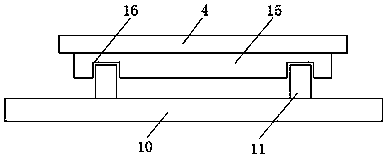
[0017] as attached figure 1 and 2 Shown: a kind of dispersing equipment for coating production, including bottom plate 1, top plate 2, cylinder 3, bearing frame 4, dispersion barrel 5, motor 6, transmission shaft 7 and stirring rod 8, it is characterized in that, described bottom plate 1 is set On the bracket 9, a vertical plate 10 is provided on the base plate 1, and a vertical stop block 11 is provided on the vertical plate 10. The top plate 2 is arranged on the vertical plate 10, and the cylinder 3 is provided On the base plate 1, a power cord 13 and a piston rod 12 are arranged on the cylinder 3, and the bearing frame 4 is arranged on the piston rod 12, and a bearing 14 and a fixed block 15 are arranged on the carrier frame 4. Both sides of the dispersing bucket 5 are provided with connecting rods 17, and the connecting rods 17 are arranged in the bearings 14, the described motor 6 is arranged on the top plate 2, and a power cord 13 is arranged on the motor 6, and the des...

Embodiment 2

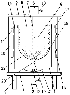
[0023] as attached image 3 Shown: a kind of dispersing equipment for coating production, including bottom plate 1, top plate 2, cylinder 3, bearing frame 4, dispersion barrel 5, motor 6, transmission shaft 7 and stirring rod 8, it is characterized in that, described bottom plate 1 is set On the bracket 9, a vertical plate 10 is provided on the base plate 1, and a vertical stop block 11 is provided on the vertical plate 10. The top plate 2 is arranged on the vertical plate 10, and the cylinder 3 is provided On the base plate 1, a power cord 13 and a piston rod 12 are arranged on the cylinder 3, and the bearing frame 4 is arranged on the piston rod 12, and a bearing 14 and a fixed block 15 are arranged on the carrier frame 4. Both sides of the dispersing bucket 5 are provided with connecting rods 17, and the connecting rods 17 are arranged in the bearings 14, the described motor 6 is arranged on the top plate 2, and a power cord 13 is arranged on the motor 6, and the described ...


PUM


Abstract

The invention discloses dispersion equipment for coating production. The dispersion equipment comprises a bottom plate, a top plate, a cylinder, a bearing rack, a dispersion drum, a motor, a transmission shaft and a stirring rod. The dispersion equipment is characterized in that the bottom plate is arranged on a bracket; the top plate is arranged on a vertical plate; the cylinder is arranged on the bottom plate; the bearing rack is arranged on the piston rod; connecting rods are arranged on two sides of the dispersion drum, and are arranged in a bearing; the motor is arranged on the top plate,and is provided with a power cord; one end of the transmission shaft is connected with the motor, and the other end of the transmission shaft is arranged in the dispersion drum; and the stirring rodis arranged on the transmission shaft in the dispersion drum. According to the dispersion equipment, the dispersion drum has a structure of rotating on the bearing rack due to the arrangement of the connecting rods, so that coating in different positions in the dispersion drum can contact the stirring rod, and can be stirred and dispersed, and the dispersion efficiency of the coating is further improved.

Description

technical field [0001] The invention relates to the technical field of paint production, in particular to dispersion equipment for paint production. Background technique [0002] Dispersing machine is a kind of mechanical equipment widely used in industry for stirring, dispersing and dissolving of coatings, inks, emulsions, adhesives and other products. Especially in the production process of coatings, the role of high-speed dispersing machines is more important. stage, the stirring speed of the disperser will directly affect the quality of the paint. For example, the patent with the application number 201120276355.5 discloses a paint disperser. Although it solves the problem of low stirring efficiency, the paint dispersion effect is not ideal. 1. The paint cannot be dispersed at different depths and angles, the work efficiency is not high, the waste of raw materials is more, and the quality of paint dispersion is not good. Contents of the invention [0003] The purpose o...

Claims


Application Information

Patent Timeline
Patent Type & Authority Applications(China)
IPC IPC(8): B01F11/00B01F15/00
CPCB01F31/50B01F31/56B01F35/53B01F2101/30
Inventor 周兆平张强汪永生
Owner 周兆平
Why Eureka
Try Eureka