Laboratory test tube automatic washing device

A washing device, laboratory technology, applied in the direction of drying gas layout, cleaning hollow objects, dryers, etc., can solve the problems of low efficiency, time-consuming, wasting time, etc., and achieve the goal of improving efficiency, increasing storage, and reducing heat. drain effect

Inactive Publication Date: 2018-12-07
徐春英
View PDF0 Cites 0 Cited by
  • Summary
  • Abstract
  • Description
  • Claims
  • Application Information

AI Technical Summary

Problems solved by technology

[0004] However, the test tube needs to be dried after cleaning to remove the water on the test tube, and it takes a lot of time to dry, which is a waste of time and the efficiency is very low

Method used


Image

  • Laboratory test tube automatic washing device
  • Laboratory test tube automatic washing device
  • Laboratory test tube automatic washing device

Examples


Embodiment 1

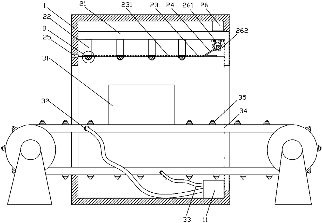
[0032] Such as Figure 1-9As shown, a laboratory test tube automatic washing device includes a box body 1, and the two sides of the box body 1 are provided with openings for the conveyor belt 34 to pass through, and the box body 1 is provided with a flushing mechanism, and the flushing mechanism includes A water spray device for rinsing the outer wall of the test tube, a rinsing device for rinsing the inner wall of the test tube and a water tank 11 for providing a water source. Below the device, through the setting of the above-mentioned flushing mechanism, the flushing mechanism can rinse the test tubes cleaned by the cleaning agent, so as to remove the cleaning agent on the washed test tubes, and through the cooperation of the water spray device and the flushing device, The inner wall and outer wall of the test tube can be cleaned at the same time, which improves the efficiency of test tube cleaning, and realizes the automation of test tube cleaning at the same time. The tes...

Embodiment 2

[0042] Such as Figure 10-12 As shown, the difference between this embodiment and Embodiment 1 is that a drying mechanism is provided on one side of the box body 1, and the drying mechanism includes a heating chamber 4 and a conveyor belt 41 for transporting the tube placement box 31. The conveyor belt 41 is installed in the heating chamber 4, and the conveyor belt 41 is arranged under the drying mechanism. Through the setting of the above drying mechanism, the test tube after cleaning can be dried, so that the test tube can quickly remove moisture, thereby The test tube can be used directly, which improves the efficiency of removing water from the test tube, and the combination of the heating chamber 4 and the conveyor belt 41 enables the test tube to be heated in the heating chamber 4 while being transported on the conveyor belt 41, which saves After heating, it needs to transport the time, while the heating chamber 4 can reduce the loss of heat, so that the effect of test t...

Embodiment 3

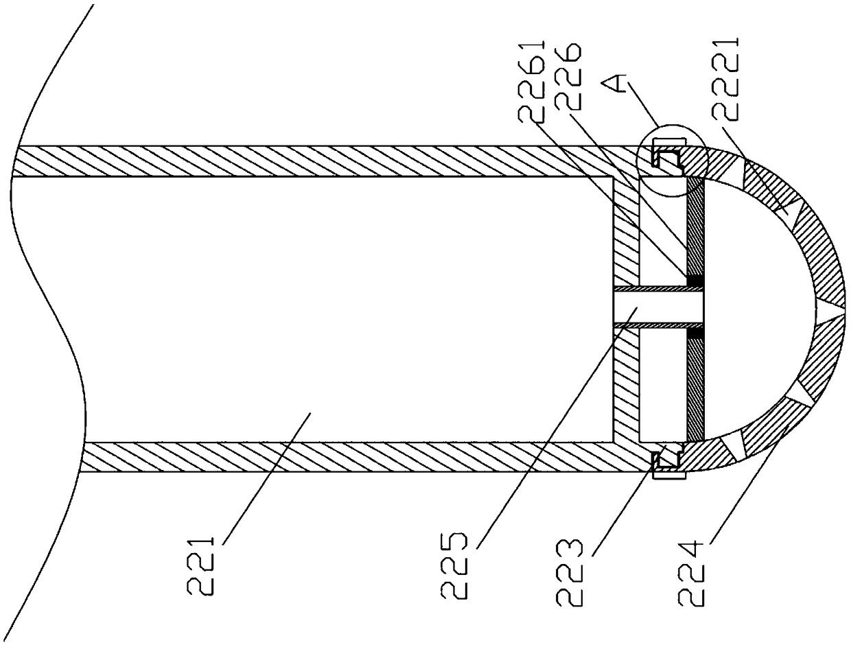
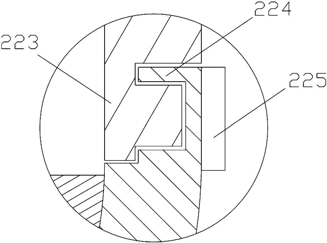
[0046] Such as Figure 13-16 As shown, the difference between this embodiment and Embodiment 1 is that: the water inlet telescopic hose 33 and the water outlet telescopic hose 32 are detachably connected to the conveyor belt 34 through a locking snap ring 5 respectively, and the above-mentioned locking clip The cooperation between the ring 5 and the conveyor belt 34 makes the water inlet telescopic hose 33 and the water outlet telescopic hose 32 detachably connected, so that when the conveyor belt 34 is damaged, the water inlet telescopic hose 33 and the water outlet telescopic hose 32 Disassemble, thereby can bleed off the water flow in the conveyor belt 34, so that the conveyor belt 34 is replaced, so that the conveyor belt 34 can be disassembled and replaced so that the conveyor belt 34 can continue to work, while making the dismounting of the conveyor belt 34 more convenient; The water outlet of the water outlet flexible hose 32 and the water inlet of the water inlet flexi...


PUM


Abstract

The invention discloses a laboratory test tube automatic washing device. The laboratory test tube automatic washing device comprises a box; a flushing mechanism is arranged in the box; the flushing mechanism comprises a water spraying device for flushing the outer walls of test tubes, and a flushing device for flushing the inner walls of the test tubes; the flushing device comprises a tube placingbox; a drying mechanism is arranged on one side of the box; the drying mechanism comprises a heating chamber, and a conveying belt for conveying the tube placing box; and the conveying belt is inserted in the heating chamber. Through arrangement of the drying mechanism, the cleaned test tubes can be dried, so that water on the test tubes can be quickly removed, the test tubes can be directly used, and the water removing efficiency of the test tubes is improved; through cooperative arrangement of the heating chamber and the conveying belt, the test tubes can be heated in the heating chamber while being conveyed on the conveying belt, so that the needed conveying time after heating is saved; and meanwhile, the heat loss of the heating chamber can be reduced, so that the drying effect of thetest tubes is better.

Description

technical field [0001] The invention belongs to the field of chemical experiment instruments, in particular to an automatic washing device for laboratory test tubes. Background technique [0002] The test tube is a commonly used instrument in the laboratory. The test tube in the laboratory needs to be washed with a cleaning agent after use. The cleaning agent will remain on the test tube after washing. The cleaning agent will affect the use of the test tube. Therefore, it is necessary to clean the remaining cleaning agent on the test tube. Rinse, at the same time, the test tube is fragile, and it is easy to break the test tube during manual cleaning. The broken test tube can easily cut the human body, which is very dangerous, and the existing test tube cleaning device cannot clean the test tubes in batches, which is very time-consuming. It needs to be dried, and it is very troublesome to place the test tube dry. If it is not placed carefully and stably, the test tube is easi...

Claims


Application Information

Patent Timeline
Patent Type & Authority Applications(China)
IPC IPC(8): B08B9/30B08B9/34B08B13/00F26B21/00
CPCB08B9/30B08B9/34B08B13/00F26B21/001
Inventor 徐春英
Owner 徐春英
Why Eureka
Try Eureka