Burr polisher for gear machining

A grinding machine and gear technology, which is used in metal processing equipment, grinding machine parts, machine tools suitable for grinding workpiece edges, etc., can solve problems such as the inability to achieve uniform grinding of gear teeth.

Inactive Publication Date: 2018-12-07
合肥银泉铸造有限责任公司
View PDF1 Cites 5 Cited by
  • Summary
  • Abstract
  • Description
  • Claims
  • Application Information

AI Technical Summary

Problems solved by technology

Since the gear is placed between the two friction discs and the end of the crank rod is inserted into the shaft hole of the gear, the end of the crank rod inserted into the shaft hole is arc-shaped when the crank rod rotates, so in order to make the crank rod can be inserted into the shaft normally In the hole, the outer diameter of the crank rod needs to be set smaller than the shaft hole, so that when the gear is in contact with the friction barrel, there is shaking up and down, and the uniform grinding of each gear tooth cannot be well achieved.

Method used


Image

  • Burr polisher for gear machining
  • Burr polisher for gear machining
  • Burr polisher for gear machining

Examples


Embodiment Construction

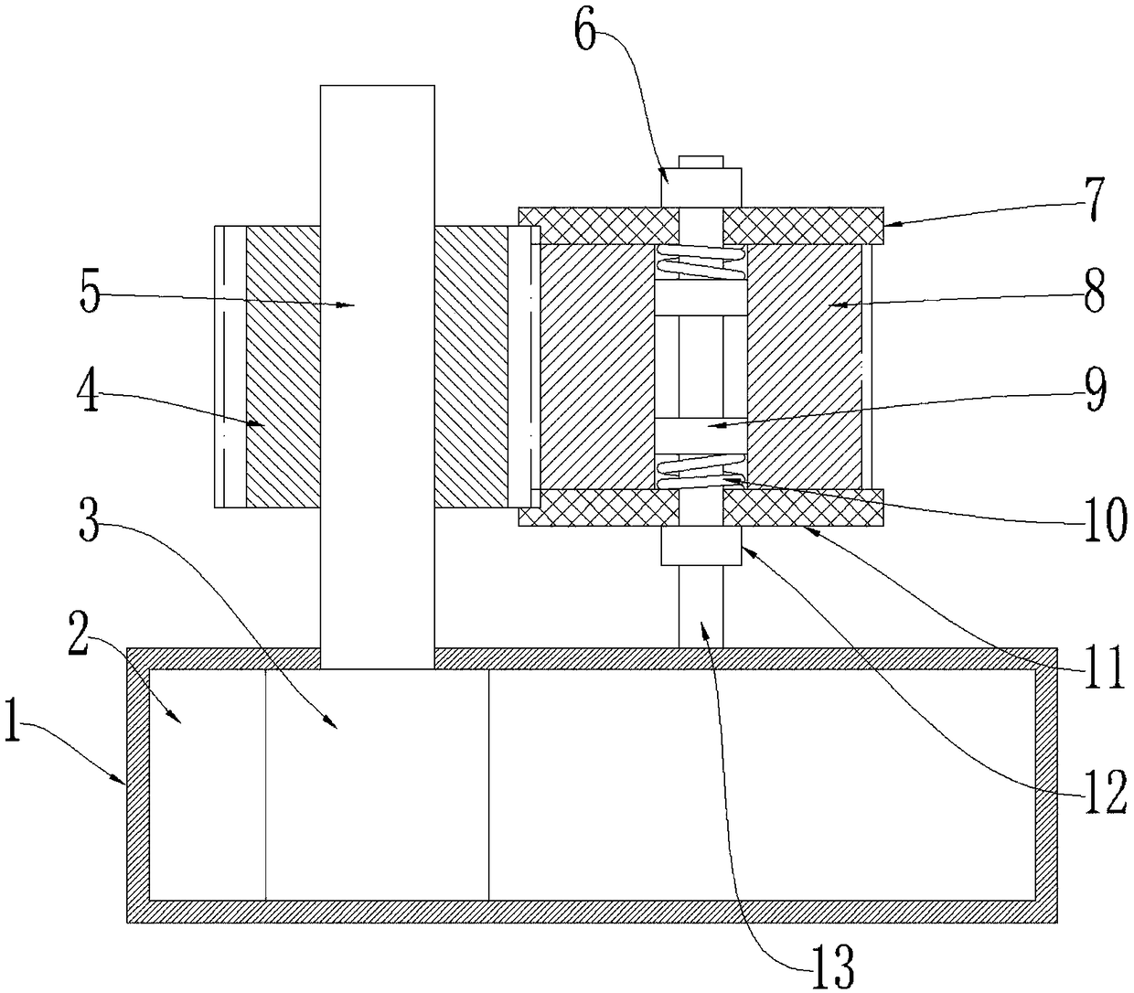
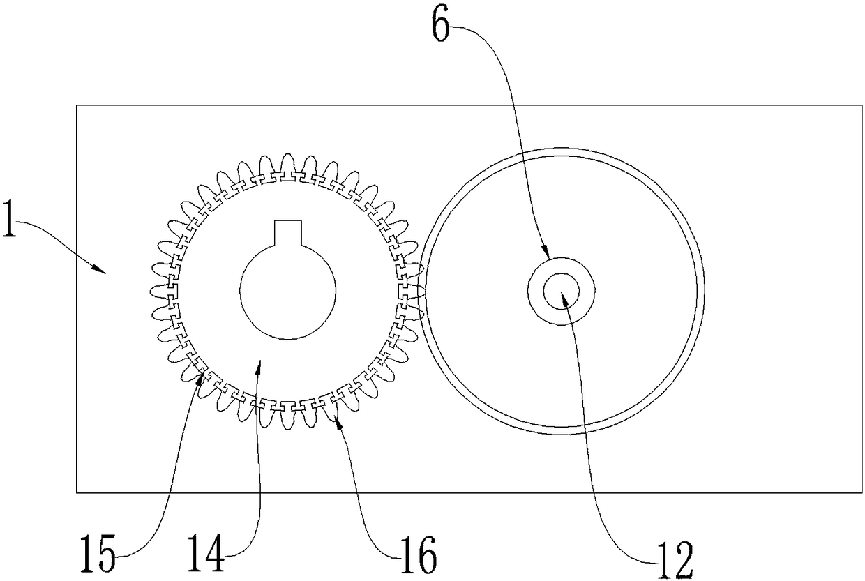
[0017] Such as figure 1 and figure 2 As shown, a burr grinder for gear processing includes a base 1, a drive chamber 2 is provided in the base 1, and a drive motor 3 is provided in the drive chamber 2. A brush shaft 5 is rotatably installed on the base 1, and the drive motor 3 drives the brush shaft 5 to rotate; a wheel brush 4 is fixed on the brush shaft 5, and the wheel brush 4 includes a brush hub 14. The outer wall of the hub 14 is evenly provided with several draw-in slots 15 extending axially along the brush hub 14, the draw-in slots 15 are provided with brush strips 16, and the brush strips 16 are tooth-shaped; the brush strips 16 and The brush hubs 14 jointly form a gear shape, and are in transmission contact with the gear to be deburred similar to gear meshing. It also includes a gear support shaft 13 fixed on the base 1, a lower friction disc 11 and an upper friction disc 7 are slidably arranged on the gear support shaft 13, and a supporting member is provided on ...


PUM


Abstract

The invention relates to a burr polisher for gear machining. The burr polisher comprises a base, the base is internally provided with a driving chamber, the driving chamber is internally provided witha driving motor, the base is rotatably provided with a brush shaft, and the driving motor drives the brush shaft to rotate; the brush shaft is fixedly provided with a wheel brush, the wheel brush comprises a brush wheel hub, the outer side wall of the brush wheel hub is evenly provided with a plurality of clamping grooves extending in the axial direction of the brush wheel hub, the clamping grooves are internally provided with brush strips, and the brush strips are in tooth shapes; and the burr polisher further comprises a gear supporting shaft fixed on the base, the gear supporting shaft isfurther slidably provided with a lower friction disc and an upper friction disc, the lower side of the lower friction disc is provided with a bearing supporting part, the upper side of the upper friction disc is provided with a compressing part, and the bearing supporting part and the compressing part are both fixed on the gear supporting shaft. By means of the burr polisher for the gear machining, comprehensive polishing on gear end surfaces and gear teeth can be realized, meanwhile, because the gear supporting shaft is vertically arranged, installation of gears to be performed burring is facilitated, the gears and a brush wheel contact highly consistent, and the polishing uniformity of each gear tooth is good.

Description

technical field [0001] The invention relates to gear processing equipment, in particular to a burr grinding machine for gear processing. Background technique [0002] Gear is a mechanical element with teeth on the wheel rim, which can continuously mesh and transmit motion and power. It appeared very early in the application of transmission. Because of the stability and continuity of transmission, it is widely used in various fields of machinery; It is one of the essential components in the gearbox. The quality of the gear determines the stability of the transmission, the accuracy of the reduction ratio, and the vibration and noise transmitted. In the cycloid reducer, the tooth profile accuracy of the gear And flatness requirements are higher. After the gear is processed by the gear processing machine tool, some burrs will inevitably remain on the surface, making the surface not smooth. This kind of gear that has just been processed is generally not sold directly, and the b...

Claims


Application Information

Patent Timeline
Patent Type & Authority Applications(China)
IPC IPC(8): B24B9/04B24B41/04B24B47/12
CPCB24B9/04B24B41/04B24B47/12
Inventor 朱晓林
Owner 合肥银泉铸造有限责任公司
Why Eureka
Try Eureka