Assembly line laser marking device for bearing model

A laser marking equipment and pipeline technology, applied in typewriters, printing and other directions, can solve the problems of inaccurate positioning and low work efficiency, and achieve the effect of improving work efficiency, facilitating unloading operations, and saving labor costs.

Inactive Publication Date: 2018-12-07
新昌县奔力机械有限公司
View PDF10 Cites 3 Cited by
  • Summary
  • Abstract
  • Description
  • Claims
  • Application Information

AI Technical Summary

Problems solved by technology

[0004] In order to solve the above technical problems, the present invention provides an assembly line laser marking equipment for bearing models to solve the problems of low efficiency of existing manual operation and prone to inaccurate positioning errors

Method used


Image

  • Assembly line laser marking device for bearing model
  • Assembly line laser marking device for bearing model
  • Assembly line laser marking device for bearing model

Examples


Embodiment

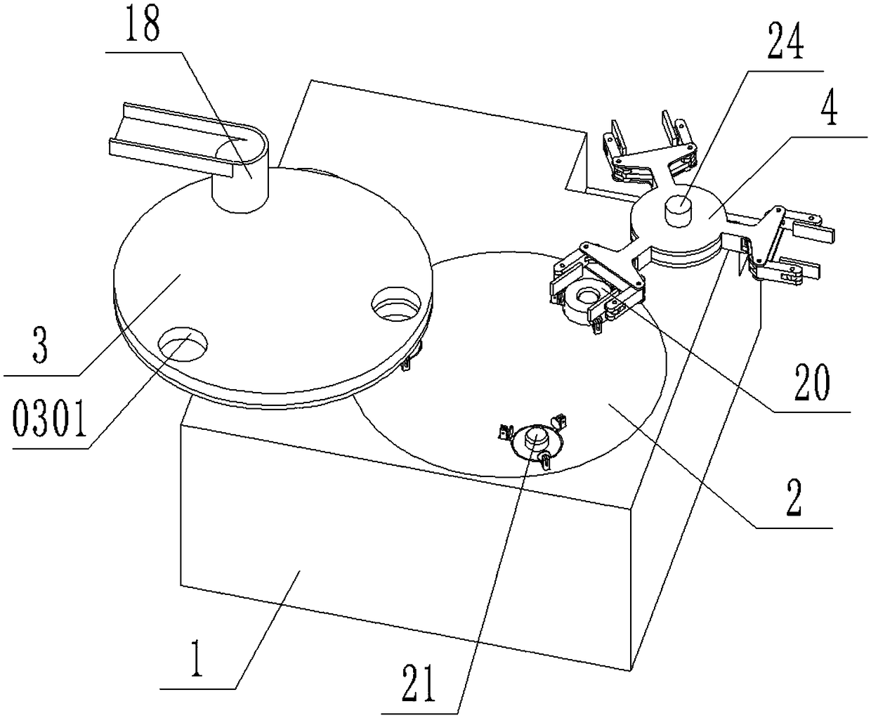
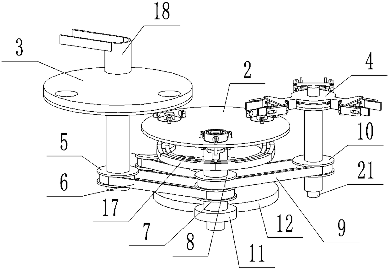
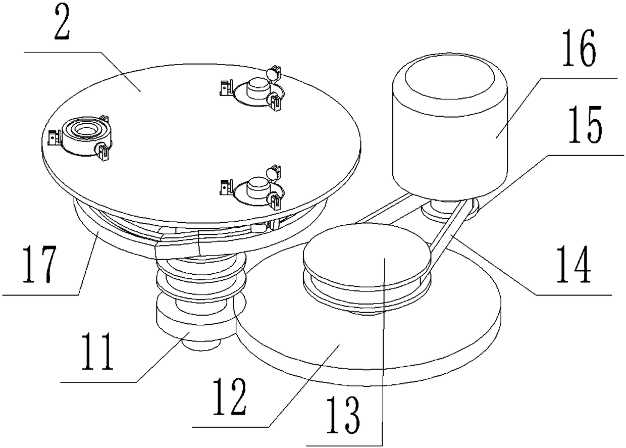
[0033] as attached figure 1 To attach Figure 8 Shown:

[0034]The invention provides an assembly line laser marking equipment for bearing models, including: a body 1, a marking workbench 2, a loading work plate 3, a pick-up hole 0301, a fixing table for an unloading manipulator 4, and a loading follower Pulley 5, loading drive belt 6, loading driving pulley 7, unloading driving pulley 8, unloading driving belt 9, unloading driven pulley 10, driven gear 11, driving gear 12, driven pulley 13 , drive belt 14, driving pulley 15, motor 16, workbench slideway 17, inlet 18, fixing plate 19, mounting hole 1901, pulling rod 20, guide wheel 2001, lifting platform 2002, tensioning block 21 , positioning table 2101, clamping lever 22, clamping block 23, unloading fixed shaft 24, cam 2401, roller 25, spring 26, push rod 27, connecting rod 28, grabbing lever 29 and grabbing block 30; Fuselage 1 The left side of the top is fixedly connected with an assembly fixing plate 19; the top of th...


PUM


Abstract

The invention provides an assembly line laser marking device for a bearing model. The device comprises a machine body, a marking workbench and a grabbing block; a group of part installation fixing plates are fixedly connected to a left side of a top part of the machine body; top parts of the part installation fixing plates are axially connected with a group of part installation work plates, and agroup of part inlet openings are arranged behind top parts of the part installation work plates; the part inlet openings are fixedly connected with an incoming part assembly line; a group of unloadingtransmission belts are wound around outer sides of unloading driven pulley wheels and unloading driving pulley wheels; a group of driven pulley wheels are fixedly and coaxially connected to a top part of a driving toothed wheel, a group of transmission belts are wound around outer sides of the driven pulley wheels and driving pulley wheels, a motor is in common electrical connection with an external control device and an external power source. The device is accurate in positioning and is capable of automatic clamping, movement or rotation can be prevented during marking processes, marking position changes can be prevented, automatic loading and unloading can be realized, labor costs can be lowered and work efficiency can be improved.

Description

technical field [0001] The invention belongs to the technical field of mechanical manufacturing, and more specifically relates to an assembly-line laser marking device for bearing models. Background technique [0002] In the production process of the bearing, it is necessary to mark the bearing to mark the bearing model and production information. Since the bearing is a standard part and the bearing is the most commonly used part, its usage is very large. Laser marking is fast because of its marking speed. The marking effect is good and widely used. In the past, laser marking machines were generally used to mark bearings, and the bearings were marked by manual loading and unloading. [0003] Based on the above, combined with the discovery of equipment in the prior art, the manual operation of the previous marking method has low work efficiency and high labor costs, which is not conducive to the demand for mass production, and manual operation is prone to inaccurate positioni...

Claims


Application Information

Patent Timeline
Patent Type & Authority Applications(China)
IPC IPC(8): B41J2/435B41J3/407
CPCB41J2/435B41J3/407
Inventor 吴朝阳石三平
Owner 新昌县奔力机械有限公司
Why Eureka
Try Eureka