Orbiting satellite recovery spacecraft device based on recoverable satellite

A technology for returnable satellites and orbiting satellites, which is applied in the field of satellites and spacecraft. It can solve the problems of on-orbit faulty satellite maintenance and the difficulty of cleaning floating objects in orbit, and achieve the effects of light weight, reduced control complexity, and improved efficiency.

Active Publication Date: 2018-12-07
ZHEJIANG UNIV
7 Cites 1 Cited by

AI-Extracted Technical Summary

Problems solved by technology

[0003] In view of the current lack of effective means to realize the maintenance of in-orbit faulty satellites and the difficulty in cleaning up in-orbit floating objects, the present invention provides an orbital sate...

Abstract

The invention discloses an orbiting satellite recovery spacecraft device based on a recoverable satellite. The orbiting satellite recovery spacecraft device comprises a flexible inflatable reconfigurable thermal protective layer, a first shock absorber system, a spacecraft platform system, a second shock absorber system and a memory metal film catcher. The spacecraft platform system is located between the memory metal film catcher and the flexible inflatable reconfigurable thermal protective layer, the flexible inflatable reconfigurable thermal protective layer is connected with the spacecraftplatform system through a first installation flange and a second installation flange, the spacecraft platform system is connected with the memory metal film catcher through a third installation flange and a fourth installation flange, and the first shock absorber system is located between the first installation flange and the second installation flange; the second shock absorber system is locatedbetween the third installation flange and the fourth installation flange; and the first shock absorber system and the second shock absorber system are used for absorbing landing impact force in the return process. The orbiting satellite recovery spacecraft device can catch or recover a non-cooperative target satellite, a spacecraft and the like in an orbit.

Application Domain

Cosmonautic vehiclesCosmonautic parts

Technology Topic

SpacecraftFlange +3

Image

  • Orbiting satellite recovery spacecraft device based on recoverable satellite
  • Orbiting satellite recovery spacecraft device based on recoverable satellite

Examples

  • Experimental program(1)

Example Embodiment

[0023] In order to make the objectives, technical solutions and advantages of the present invention clearer, the following examples are used in conjunction with the accompanying drawings to further describe the orbiting satellite recovery spacecraft device based on the returnable satellite of the present invention. It should be understood that the specific embodiments described here are only used to explain the present invention, but not to limit the present invention.
[0024] The serial numbers assigned to the components in the present invention, such as "first", "second", etc., are only used to distinguish the described objects and do not have any sequence or technical meaning. In the present invention, unless expressly stipulated and defined otherwise, the first feature “on” or “under” the second feature may be in direct contact with the first and second features, or the first and second features may be indirectly through an intermediary. contact. Moreover, the "above", "above" and "above" of the first feature on the second feature may mean that the first feature is directly above or obliquely above the second feature, or simply means that the level of the first feature is higher than the second feature. The “below”, “below” and “below” of the second feature of the first feature may mean that the first feature is directly below or obliquely below the second feature, or it simply means that the level of the first feature is smaller than the second feature.
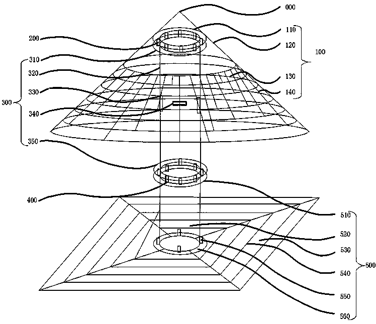
[0025] See Figure 1 to Figure 2 , The present invention provides an orbiting satellite recovery spacecraft device 000 based on a returnable satellite. The spacecraft device 000 can capture non-cooperative target satellites, spacecraft, or floating objects in orbit, so as to clean up orbit malfunctioning satellites. , Orbital floats and the purpose of recovering malfunctioning satellites. For example, the present invention can be applied to the capture, cleaning and return of earth orbit faulty satellites, spacecraft, and floating objects to realize the recovery and failure analysis of earth orbit faulty satellites, and provide technical support for subsequent satellite design; recovery has high value Satellite components and data storage units, etc.; clean up floating objects in usable orbits to reduce the impact on existing and newly launched satellites or spacecraft.
[0026] The orbiting satellite recovery spacecraft device 000 based on a returnable satellite includes a flexible inflatable reconfigurable thermal protection layer 100, a first shock absorber system 200, a spacecraft platform system 300, a second shock absorber system 400, and a memory metal film capture 器500;
[0027] The spacecraft platform system 300 is located between the memory metal film trap 500 and the flexible reconfigurable heat protection layer 100. The flexible inflatable reconfigurable heat protection layer 100 passes through the first mounting flange 110 and the second mounting flange 110. The mounting flange 310 realizes the connection with the spacecraft platform system 300, and the spacecraft platform system 300 realizes the connection with the memory metal film trap 500 through the third mounting flange 350 and the fourth mounting flange 510. The first reduction The shock absorber system 200 is located between the first mounting flange 110 and the second mounting flange 310; the second shock absorber system 400 is located between the third mounting flange 350 and the fourth mounting flange. Between flange 510.
[0028] The first shock absorber system 200 and the second shock absorber system 400 are used to absorb the impact force of landing when returning.
[0029] The flexible, inflatable and reconfigurable thermal protection layer 100 is stored in its aerodynamic thermal protection shell 120 before landing, and only starts to be inflated and deployed when landing. The power thermal protection shell 120 is a metal outsole, which is used to protect the interior from heat damage while advancing, and has a storage function. The spacecraft platform system 300 is mainly responsible for the on-orbit measurement and control, satellite management, and data communication of the entire spacecraft device 000, and controls the memory metal film capture device 500 to capture the target in orbit, and provides the power required for attitude control when returning. The memory metal film trap 500 is in a folded state before launch. The memory metal film 530 is stored in the trap device compartment 520. When it is necessary to capture an on-orbit target, the memory metal film 530 is distributed on the surface of the memory metal film 530. The circuit structure 540 is expanded, and the target satellite is fixed after capture. The memory metal film 530 is a film made of memory metal, which can expand or contract under different voltages. The visual perception system 550 carried by it can assist in the capture of the target during the entire capture process.
[0030] Specifically, the flexible inflatable reconfigurable heat protection layer 100 includes a first mounting flange 110, an aerodynamic heat protection housing 120, an inflatable heat protection tube 130, and a heat protection tube bandage 140. The first mounting flange 110 is used to realize the connection between the flexible, inflatable and reconfigurable thermal protection layer 100 and the spacecraft platform system 300. The aerodynamic heat protection housing 120 and the first mounting flange 110 are an integral structure. Before the flexible inflatable reconfigurable heat protection layer 100 is unfolded, the inflatable heat protection tube 130 is in an inflated and folded state, and is installed in the aerodynamic heat protection shell 120 together with the heat protection tube bandage 140. After receiving the opening signal, the inflatable thermal protection tube 130 begins to chemically react through the filled chemical powder-like object, and generates enough gas to open the thermal protection tube bandage 140, which is connected to the aerodynamic force through the thermal protection tube bandage 140 The thermal protection shell 120 forms an organic whole.
[0031] As an implementation manner, the exemplary spacecraft platform system 300 includes a second mounting flange 310, a spacecraft equipment bay 320, a spacecraft communication system 330, a spacecraft thruster system 340, and a third mounting flange 350. The second mounting flange 310 is used to connect with the first mounting flange 110 of the flexible inflatable reconfigurable thermal protection layer 100. The third mounting flange 350 is used to connect with the fourth mounting flange 510 of the memory metal film trap 500. The spacecraft equipment cabin 320 is mainly used for general instruments and equipment required for the normal operation of the spacecraft platform, such as on-board computers, attitude control systems, power management systems, communication systems, orbit control systems, thermal control systems, and cabin structure systems. The spacecraft communication system 330 is located inside the spacecraft equipment cabin 320, and is mainly responsible for communication and data communication throughout the life cycle of the orbiting satellite recovery spacecraft of the returnable satellite. The spacecraft thruster system 340 is located outside the spacecraft equipment compartment 320, adopts air-conditioning propulsion technology, and is evenly distributed in its four quadrants to provide on-orbit control and return time for the orbiting satellite recovery spacecraft of the entire returnable satellite Attitude and orbit control.
[0032] As an implementation manner, the memory metal film trap 500 includes a fourth mounting flange 510, a trap device compartment 520, a memory metal film 530, a memory metal circuit structure 540, a visual perception system 550, and an adapter mounting flange 560. The fourth mounting flange 510 realizes the connection with the spacecraft platform system 300 through the third mounting flange 350. The trap equipment compartment 520 is located between the fourth mounting flange 510 and the adapter mounting flange 560, and is mainly used to place the memory metal film 530 of the folded memory metal trap and necessary instruments and equipment. The memory metal circuit structure 540 is evenly distributed on the memory metal film 530, and is fixed on the trap device compartment 520 through the memory metal film 530. The visual perception system 550 is fixed outside the capture device compartment 520, and is mainly used to realize visual perception during the capture process to ensure the success of the capture. The adapter mounting flange 560 is located at the end of the memory metal film trap 500 and is mainly used for docking with the launch vehicle.
[0033] The above-mentioned embodiments only express several implementation modes of the present invention, and the descriptions are relatively specific and detailed, but they should not be understood as limiting the protection scope of the present invention. It should be pointed out that for those of ordinary skill in the art, without departing from the concept of the present invention, several modifications and improvements can be made, and these all fall within the protection scope of the present invention.

PUM

no PUM

Description & Claims & Application Information

We can also present the details of the Description, Claims and Application information to help users get a comprehensive understanding of the technical details of the patent, such as background art, summary of invention, brief description of drawings, description of embodiments, and other original content. On the other hand, users can also determine the specific scope of protection of the technology through the list of claims; as well as understand the changes in the life cycle of the technology with the presentation of the patent timeline. Login to view more.

Similar technology patents

Systems and methods for notifying multiple hosts from an industrial controller

ActiveUS8150959B1reusable block of code very difficultimprove efficiency
Owner:ROCKWELL AUTOMATION TECH

Hybrid OLED having improved efficiency

InactiveUS20080284317A1improve efficiency
Owner:GLOBAL OLED TECH

MIMO-OFDM transmitter

InactiveUS20070253504A1improve efficiencyreduce time
Owner:FUJITSU LTD

Classification and recommendation of technical efficacy words

  • light in mass
  • Improve efficiency

Graphene heat radiation paint, preparation method and applications

ActiveCN105273540Alight in massHigh film strength
Owner:SHENZHEN GUOCHUANG JIAWEI GRAPHENE TECH CO LTD

High-voltage line inspection robot

Owner:SHENZHEN JINGZHI MACHINE

Deployable surface device with fixed truss structure

InactiveCN102011922Alight in massLow areal density
Owner:XIDIAN UNIV

Aircraft with changeable wing shape

Owner:HARBIN INST OF TECH

Large-angle all-round-lighting LED bulb

InactiveCN103712106AOptimize space arrangementlight in mass
Owner:BONSHINE OPTICAL ELECTRON TECH
Why Eureka
Try Eureka