Rotary automatic cone retractor
A retractable and rotary technology, applied to roads, road signs, traffic signals, etc., can solve the problems of dangerous working environment, low work efficiency, heavy workload, etc.
- Summary
- Abstract
- Description
- Claims
- Application Information
AI Technical Summary
Problems solved by technology
Method used
Image

Examples
Embodiment 1
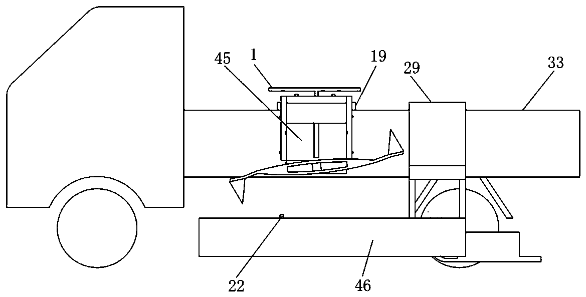
[0080] The working method of deploying the cone 44 by the rotary cone automatic retracting machine is to install the rotary cone automatic retracting machine on the left side of the vehicle, such as figure 1 Shown, take the mode that vehicle travels forward and lay cone 44, be in the following steps:
[0081] (1.1) Deployment preparation
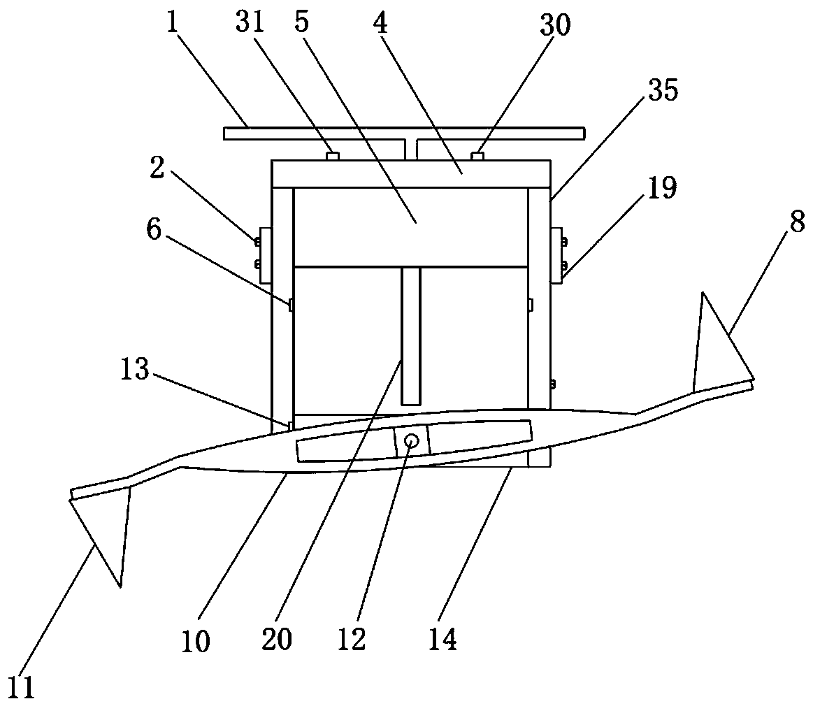
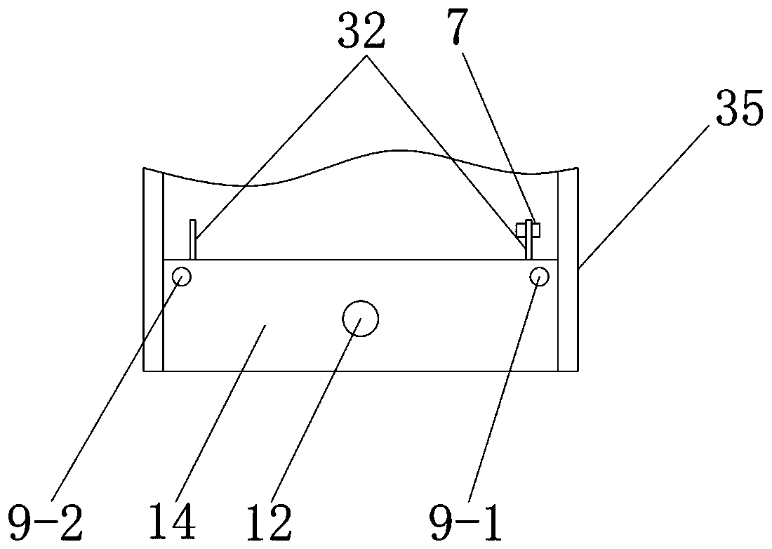
[0082] Before the operation of deploying the cone 44, such as Figure 8 As shown, first adjust the right ends of the two guide frames 26 to the parallel position according to the position of the tension adjustment hole 43 through the tension hook 27; the photoelectric switch I7 is installed on the photoelectric switch bracket I32 on the right side of the power box 14; the photoelectric switch II23 is installed On the photoelectric switch bracket Ⅱ36;
[0083] (1.2) clockwise rotation
[0084] Start the vehicle to run forward, turn on the power switch 30, turn on the steering switch I31 to indicate the position of the photoelectric switch...
Embodiment 2
[0091] The rotary cone automatic retractable machine collects the cone 44 working method, and the rotary cone automatic retractable machine is installed on the left side of the vehicle, such as figure 1 Shown, take the mode that the vehicle travels backwards to collect the cone 44, the cone 44 is pre-placed behind the left side of the vehicle, in the following steps:
[0092] (2.1) Collection preparation
[0093] Before the collection cone 44 operates, such as Figure 8 As shown, first adjust the right ends of the two guide frames 26 to the opening angle according to the position of the tension adjustment hole 43 through the tension hook 27, and align the opening angles of the two guide frames 26 right ends with the cones on the ground on the right side. Tube 44; photoelectric switch I7 is installed on the photoelectric switch bracket I32 on the right side of the power box 14; photoelectric switch II23 is installed on the photoelectric switch bracket II36;
[0094] (2.2) Ro...
Embodiment 3
[0102] The rotary cone automatic retractable machine deploys the cone 44 working method, and the rotary cone automatic retractable machine is installed on the left side of the vehicle, such as figure 1 As shown, adopting the mode that the vehicle travels backwards to lay out the cone 44 lies in the following steps:
[0103] (3.1) Deployment preparation
[0104] Before deploying the cone 44, first reverse the left and right direction of the cone retracting system 45, refer to figure 1 , that is, adjust the pair of guide plates 25 on the left side to the right side, and adjust the pair of guide frames 26 on the right side to the left side, and then connect them to the bracket II 29 through bolts; The left ends of the two guide frames 26 are in a parallel position; the photoelectric switch I7 is adjusted and installed on the photoelectric switch bracket I32, and the photoelectric switch II23 is installed on the left photoelectric switch bracket II36 of the power box 14, refer t...
PUM
 Abstract
Description
Claims
Application Information
 - R&D
- Intellectual Property
- Life Sciences
- Materials
- Tech Scout
- Unparalleled Data Quality
- Higher Quality Content
- 60% Fewer Hallucinations
Browse by: Latest US Patents, China's latest patents, Technical Efficacy Thesaurus, Application Domain, Technology Topic, Popular Technical Reports.
© 2025 PatSnap. All rights reserved.Legal|Privacy policy|Modern Slavery Act Transparency Statement|Sitemap|About US| Contact US: help@patsnap.com