Railway rescue station with smoke prevention and exhaust and personnel emergency evacuation functions

A technology for emergency evacuation and rescue stations, applied in the field of railway rescue stations, can solve the problems of increasing tunnel cross-sectional area, large shaft size, and construction waste, so as to reduce the increase in the number of shafts, reduce the increase in shaft size, and reduce construction costs. The effect of technical difficulty

Active Publication Date: 2018-12-07
HEFEI UNIV OF TECH
View PDF10 Cites 13 Cited by
  • Summary
  • Abstract
  • Description
  • Claims
  • Application Information

AI Technical Summary

Problems solved by technology

[0006] (1) Similar rescue stations are generally set in the middle of the tunnel, with a relatively deep burial depth, and only shafts can be selected for parallel pilot tunnels or parallel service tunnels, which will lead to larger shaft sizes, or increase the number of shafts, and increase construction technical difficulty and cost
[0007] (2) Rescue stations still need to be set up at both ends of the tunnel for fire fighting and rescue work, resulting in unnecessary construction waste of the project
[0010] (2) Setting up a separate flue exhaust directly above the tunnel will inevitably increase the construction cost
[0011] (3) The space reserved above the tunnel is used as a flue exhaust channel, which is not conducive to daily maintenance and repair
[0012] (4) If a certain space is reserved separately on the side of the tunnel to separate a smoke exhaust duct, it will inevitably increase the cross-sectional area of ​​the tunnel, which will increase the construction cost of the tunnel soil
[0013] (5) If smoke exhaust ducts are installed separately on both sides of the double-hole single-lane tunnel, that is, each exhaust duct can only serve one tunnel, which is wasteful
[0014] (6) For extra-long tunnels, the simple longitudinal ventilation method has poor smoke exhaust effect
When the vehicle stops completely at the rescue station, due to the effect of the initial piston wind, the smoke accumulated in the tunnel behind the train will be pushed forward and quickly diffuse into the rescue station, and the smoke spread law at this time after the train stops at the rescue station has Great randomness, which is extremely unfavorable for rescue station personnel evacuation and fire fighting and rescue

Method used


Image

  • Railway rescue station with smoke prevention and exhaust and personnel emergency evacuation functions
  • Railway rescue station with smoke prevention and exhaust and personnel emergency evacuation functions
  • Railway rescue station with smoke prevention and exhaust and personnel emergency evacuation functions

Examples


Embodiment example 1

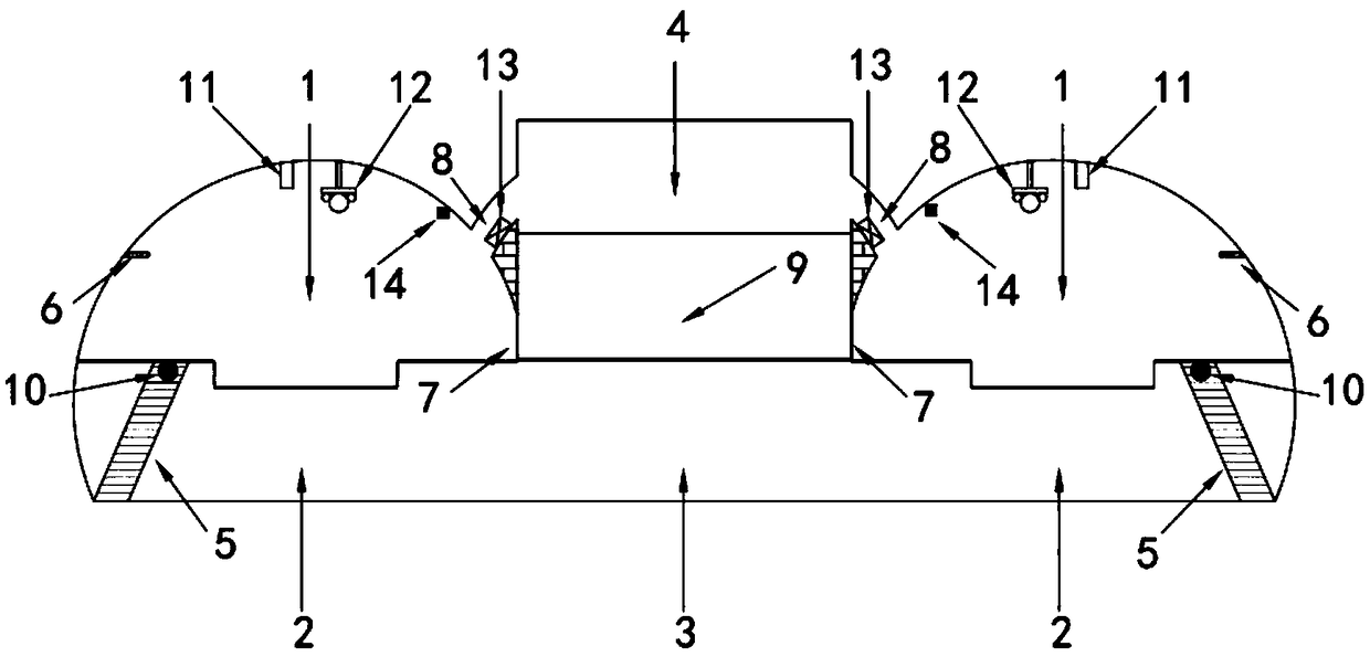
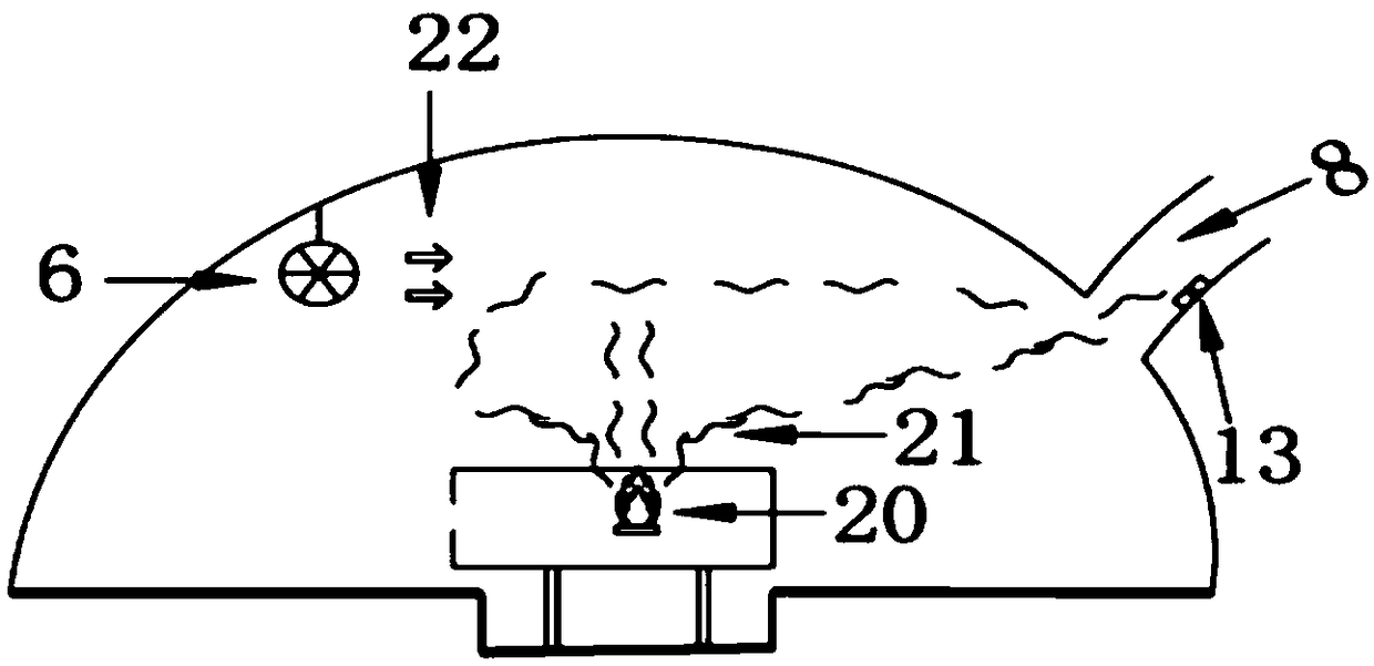
[0059] When the tail of the train was on fire, in this case, after the fire train drove into the rescue station, all the doors and windows of the train at the downstream end of the rescue station were opened, and the passengers entered the tunnel evacuation layer 2 by the evacuation stairs 5 and then entered the rest of the tunnel by the evacuation passage 3. The fire tunnel awaits rescue. Open the remote control smoke exhaust damper 13 in the smoke exhaust port 8 downstream of the rescue station, and simultaneously move the jet fan unit 12 to determine the smoke exhaust direction from the upstream of the burning part of the fire train, and then gradually move to the fire source position. The gas concentration and flow velocity are adjusted to different positions and the wind force cooperates with the smoke exhaust port 8 for longitudinal smoke exhaust and can prevent the downstream tunnel smoke from flowing backward. At the same time, the fire extinguishing chamber 11 is move...

Embodiment example 2

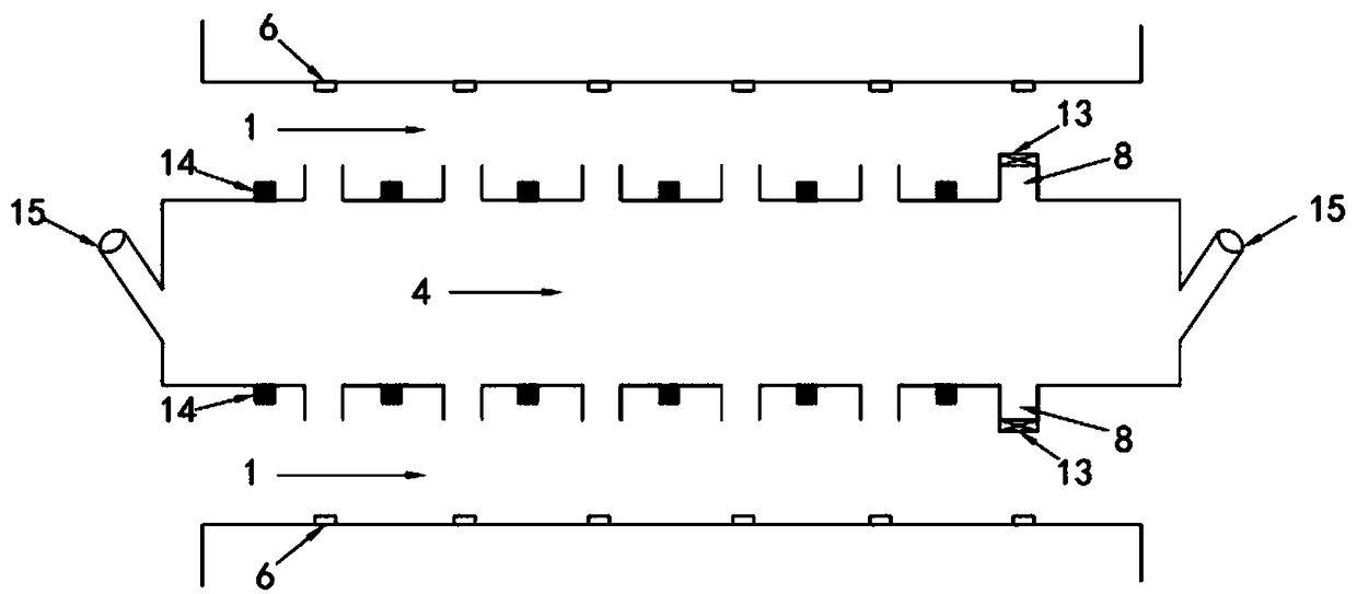
[0061] When the middle of the train is on fire, when the train stops at the rescue station, the fire source is in the middle of the rescue station. If the fire cannot be exhausted and extinguished in time, the smoke will quickly spread to the entire rescue station. In this case, the rescue measure is that all the doors and windows of the train are all opened, and the passengers enter the tunnel evacuation layer 2 by the evacuation stairs 5 and then enter the unfired tunnel by the evacuation passage 3 and wait for rescue. Fire smoke detection modules 14 and directional jet fans 6 are installed longitudinally along both sides of the tunnel in the track area of ​​the railway rescue station, and a mobile fire extinguishing chamber 11 and a mobile jet fan unit 12 are installed directly above the top of the tunnel. At this time, the fire smoke detection module 14 of the rescue station monitors the location of the fire source and the smoke concentration in the tunnel in real time. Th...


PUM


Abstract

The invention discloses a railway rescue station with smoke prevention and exhaust and personnel emergency evacuation functions. The railway rescue station is divided into an upper-layer structure, amiddle-layer structure and a lower-layer structure; the upper layer of the station is a smoke exhaust channel; the middle layer of the station is a rescue station body; the lower layer of the stationis an evacuation channel; a tunnel in the longitudinal range of the railway rescue station is composed of an upper-layer train tracking area and a lower-layer evacuation layer, and smoke exhaust portsare evenly formed in the upper portion of the inner side of a track of the upper-layer train tracking area; each smoke exhaust port is internally provided with a remote control smoke exhaust air valve; each smoke exhaust port is provided with a fire smoke detection module; the opposite sides of each smoke exhaust port are provided with directional jet fans; the upper portion of the train trackingarea is provided with mobile jet fan groups and movable fire extinguishing bins separately; escape staircases are arranged between the upper-layer train tracking area and the lower-layer evacuation layer. The railway rescue station mainly solves the problem that an evacuation platform cannot be arranged on a conventional rescue station for two two-hole single-line tunnel with short transverse distance, and the efficiency of smoke exhaust and personnel evacuation is improved.

Description

technical field [0001] The invention relates to the field of traffic safety, in particular to a railway rescue station with functions of smoke prevention and exhaustion and personnel emergency evacuation. Background technique [0002] With the continuous development of railways, the number of extra-long railway tunnels is also increasing. A railway tunnel is a building that lays a railway underground or underwater for the passage of motor vehicles. The tunnel is a semi-enclosed space. Once a fire that is difficult to extinguish occurs on the train, the temperature and smoke in the tunnel will accumulate rapidly. When the power of the train is not enough to make it reach the exit, fire fighting and personnel evacuation will be very difficult. Especially when the fire occurs far away from the tunnel exit, the failure of people to evacuate in time is more likely to cause panic among the masses, resulting in casualties such as trample injuries. [0003] Therefore, according to...

Claims


Application Information

Patent Timeline
Patent Type & Authority Applications(China)
IPC IPC(8): E21F11/00E21D9/14E21F1/00
Inventor 唐飞邓磊王强董满生丁建勋石琴
Owner HEFEI UNIV OF TECH
Why Eureka
Try Eureka