High-temperature and high-pressure rigidity seal hydrophobic ball valve

A high-temperature, high-pressure, hard-sealed technology, applied to shaft seals, valve details, valve devices, etc., can solve problems such as serious erosion of sealing surfaces, short service life of valves, and impact on unit efficiency, so as to achieve good overall sealing performance and ensure stability , Improving the service life and the effect of sealing performance

Pending Publication Date: 2018-12-07
KROM WUXI FLUID CONTROL
View PDF1 Cites 2 Cited by
  • Summary
  • Abstract
  • Description
  • Claims
  • Application Information

AI Technical Summary

Problems solved by technology

[0004] Although this pneumatic high-temperature and high-pressure hydrophobic ball valve has a sloped groove on the outer surface at the position where the valve body is connected to the bracket, it can effectively reduce welding deformation during welding, especially to protect the valve during post-weld heat treatment; The limit groove and the limit device on the bracket are set on the coupling, which can control the maximum range of opening and closing, and ensure that it can be fully opened and fully closed accurately. High-speed flow, and the medium directly faces the sealing surface of the valve core and valve seat, so the sealing surface is severely eroded, and the service life of the valve is short, which seriously affects the efficiency of the unit and threatens safe operation

Method used


Image

  • High-temperature and high-pressure rigidity seal hydrophobic ball valve
  • High-temperature and high-pressure rigidity seal hydrophobic ball valve
  • High-temperature and high-pressure rigidity seal hydrophobic ball valve

Examples


Embodiment 1

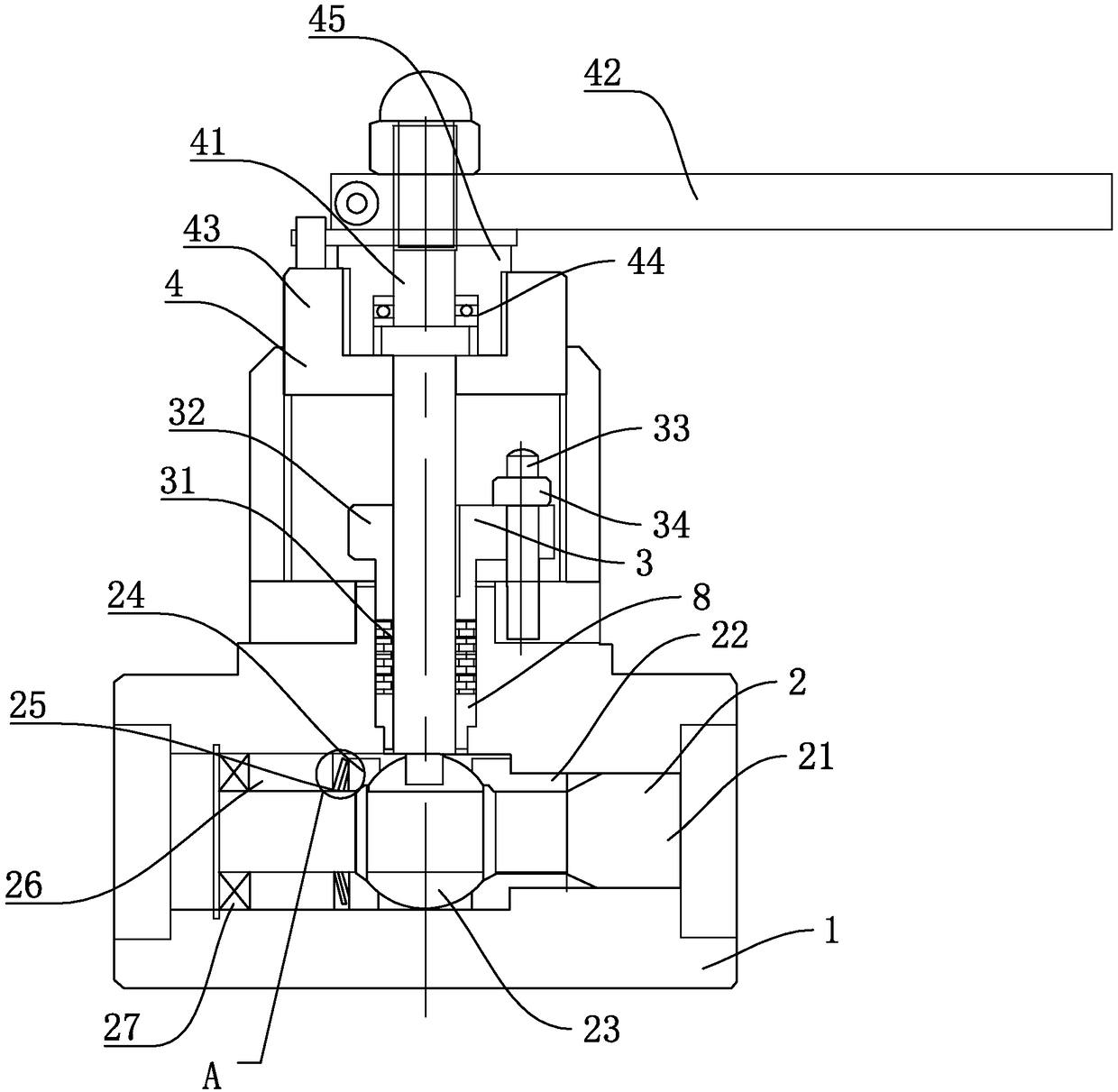
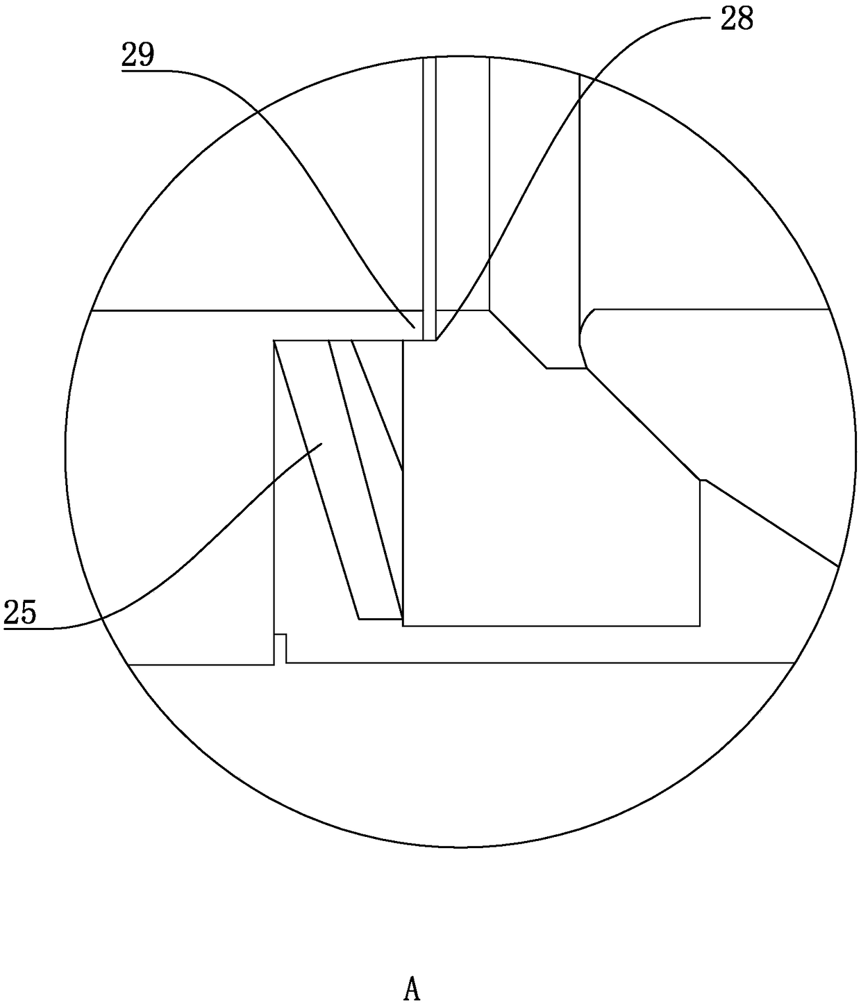
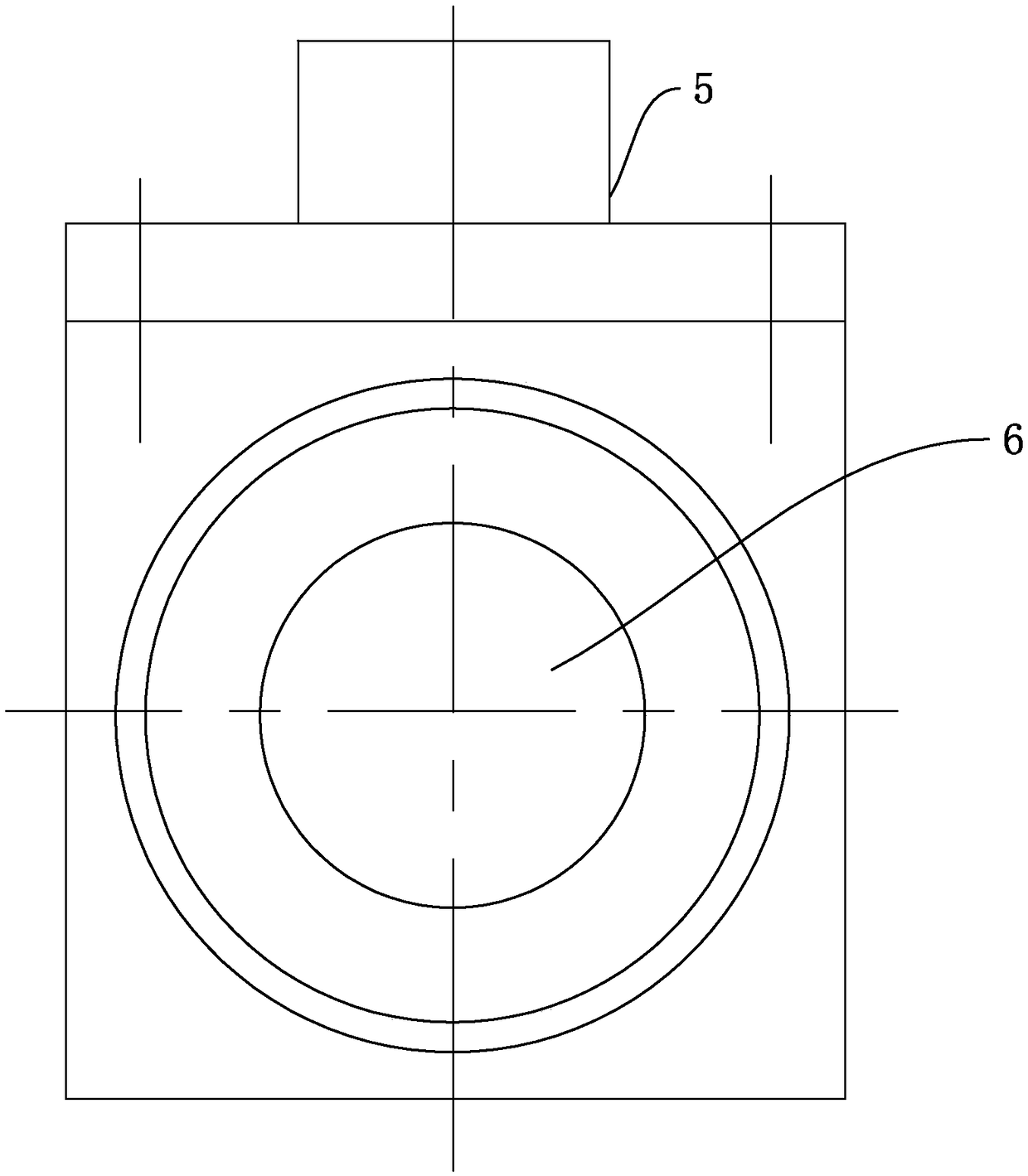
[0027] Example 1: A high temperature and high pressure hard-sealed hydrophobic ball valve, as shown in Figure 1, figure 2 and image 3 As shown, the valve body 1 is included, and the valve body 1 is provided with a sealing device 2. The sealing device 2 includes a channel 21 located in the valve body 1, and a fixed valve seat 22 is fixedly welded on the right side of the valve body 1. There is also a valve seat 22 in the valve body 1 There is a valve ball 23 that forms the main sealing valve with the fixed valve seat 22, and a movable valve seat 24 is provided on the other side of the channel 21, and a compression spring 25 that fits the valve ball 23 is also provided on the movable valve seat 24, and The compression spring 25 is also provided with an adjusting bonnet 26 at one end away from the valve ball 23, and a spring retaining ring 27 is also provided at the side of the adjusting bonnet 26 away from the compression spring 25, and an inner hole step is also provided at t...


PUM


Abstract

The invention discloses a high-temperature and high-pressure rigidity seal hydrophobic ball valve, aiming to provides a ball valve resistant to high temperature and high pressure. According to the technical scheme, the high-temperature and high-pressure rigidity seal hydrophobic ball valve comprises a valve body, the valve body is internally provided with a sealing device, and the sealing device comprises the valve body and a channel in the valve body; a fixed valve seat is fixedly welded to the right side of the valve body, and the valve body is further internally provided with a valve ball which forms a main seal with the fixed valve seat; a moving valve seat is arranged on the other side of the channel, and the moving valve seat is further provided with a pressure spring attached to thevalve ball; an adjusting valve seat is further arranged at the end, away from the valve ball, of the pressure spring, and a spring retaining ring is further arranged on the side, away from the pressure spring, of the adjusting valve cover; and an inner hole step is further arranged at the top end of the moving valve seat, and a lip tip for inserting the inner hole step is arranged at one end of the adjusting valve cover.

Description

technical field [0001] The invention relates to the field of ball valve equipment, in particular to a high-temperature, high-pressure hard-sealed hydrophobic ball valve. Background technique [0002] Hard-sealed ball valve, manual cast steel hard-sealed ball valve body surface adopts advanced spraying technology, through the treatment of various working conditions, the highest hardness can reach HRC78. The treatment of the sealing surface of the valve seat can reach a maximum hardness of HRC72. The ball and the seat are matched and ground, and all sealing areas of the entire sealing surface of the ball valve are precision ground. Suitable for high temperature and high pressure water, steam, petroleum, coal, fiber, viscous and corrosive media, as well as media with particles. The metal seal ball valve has two structures of floating ball and fixed ball. The metal seat ring is in contact with the spherical surface, and the seat ring and the spherical surface form a seal throu...

Claims


Application Information

Patent Timeline
Patent Type & Authority Applications(China)
IPC IPC(8): F16K5/06F16K5/20F16K5/08F16K41/02F16K27/06
CPCF16K5/0694F16K5/08F16K5/204F16K27/067
Inventor 朱国财朱培贤朱培兴朱培斌陈尚丰谢卫红黄益华刘康
Owner KROM WUXI FLUID CONTROL
Why Eureka
Try Eureka