Detachable ultrasonic guided-wave sensor and mounting method thereof

An ultrasonic guided wave and sensor technology, applied in the field of sensors, can solve problems such as poor uniformity of energy coupling between sensors and structures, low structural life of bonded sensors, and inability to effectively detect, etc., to achieve strong standardization and avoid calibration, etc. work, ensuring consistent results

Inactive Publication Date: 2018-12-07
大连君晟科技有限责任公司
View PDF5 Cites 6 Cited by
  • Summary
  • Abstract
  • Description
  • Claims
  • Application Information

AI Technical Summary

Problems solved by technology

Such structures are often subjected to complex, long-term fatigue loads and unexpected impact loads, etc., and are prone to inconspicuous damage. Therefore, the safety inspection of plate and shell structures has always been concerned.
These two methods have the following problems: 1) The life of the bonded sensor may be lower than the life of the structure
Sensors fail earlier than structures and eventually fail to detect effectively
2) Embedded sensors are not suitable for thin-walled metal structures and cannot be replaced
However, this type of vacuum adsorption installation method still has some problems in actual operation, such as the inability to guarantee the vacuum degree during vacuum adsorption, resulting in poor uniformity of energy coupling between the sensor and the structure, which affects the actual detection effect

Method used


Image

  • Detachable ultrasonic guided-wave sensor and mounting method thereof
  • Detachable ultrasonic guided-wave sensor and mounting method thereof

Examples


Embodiment 1

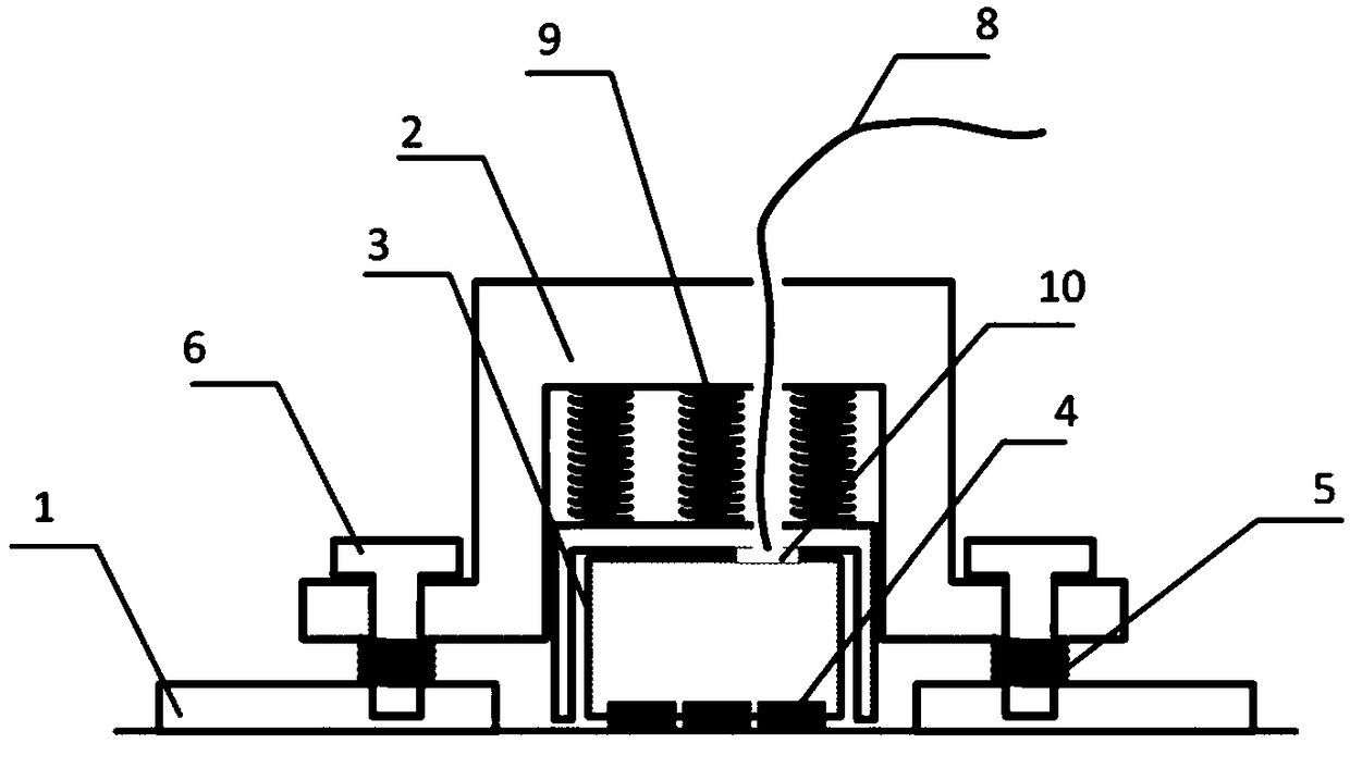
[0025] Embodiment 1, an installation method of a detachable ultrasonic guided wave sensor:

[0026] The base 1 is fixed on the surface of the structure. After the probe 3 is installed on the shell 2 through the lead interface 10, the shell 2 is installed on the base 1 with the bolt 6. When the bolt 6 is tightened, due to the gap between the probe 3 and the shell 2 Due to the function of the connected spring 9, the probe will be gradually pressed against the structure. After installation, the coupling between the probe and the structure is stable, and the corresponding data acquisition equipment is used to excite / receive ultrasonic guided waves to realize damage detection. After the work of the sensor is finished, the bolt 6 is unscrewed, the shell 2 is removed from the base 1, and the main body of the sensor is recovered.

Embodiment 2

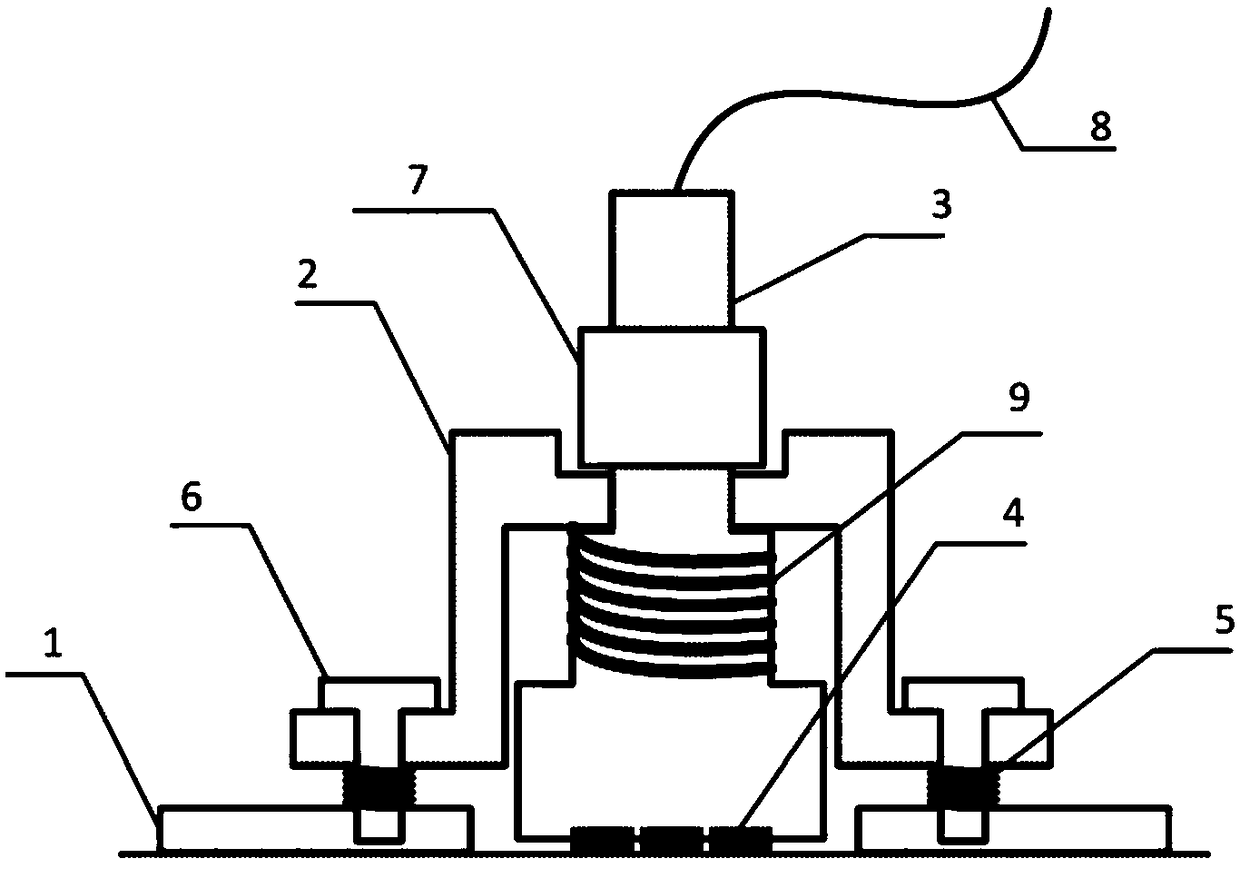
[0027] Embodiment 2, an installation method of a detachable ultrasonic guided wave sensor with a stop nut:

[0028] The base 1 is fixed on the surface of the structure. After the probe 3 is installed on the shell 2, the shell 2 is installed on the base 1 with the bolt 6. When the bolt 6 is tightened, due to the spring 9 connected between the probe and the shell and the limit Due to the function of the bit nut 7, the probe 3 will be gradually pressed against the structure. After installation, the coupling between the probe 3 and the structure is stable, and the corresponding data acquisition equipment is used to excite / receive ultrasonic guided waves to realize damage detection. After the work of the sensor is finished, the bolt 6 is unscrewed, the shell 2 is removed from the base 1, and the main body of the sensor is recovered.


PUM


Abstract

The invention discloses a detachable ultrasonic guided-wave sensor and a mounting method thereof. Compared with the traditional point-to-point nondestructive detection, the device adopts the ultrasonic guided-wave of a PZT wafer for realizing rapid damage detection for the structure; the detection efficiency is greatly increased due to the characteristic that traversing search for the structure isnot required; the operation for mounting the detachable sensor is simple; due to strong normalization of operation, the consistency of energy coupling is guaranteed; the aged or damaged sensor can beconveniently replaced; the operations, such as calibration for the sensor, are avoided; accuracy and reliability of damage detection are overall increased; the detachable sensor provided by the invention has the advantages of simple structure, easiness in industrialization and wide application in damage detection for large-scale engineering structures, such as water conservancy civil, bridge construction and mechanical equipment.

Description

technical field [0001] The invention relates to the technical field of sensors, in particular to a detachable ultrasonic guided wave sensor and an installation method thereof. Background technique [0002] Plate and shell structures are widely used in large-scale engineering structures such as aerospace and civil machinery. Such structures are often subjected to complex and long-term fatigue loads and unexpected impact loads, etc., and are prone to inconspicuous damage. Therefore, the safety inspection of plate and shell structures has always been concerned. [0003] In recent years, the detection technology based on ultrasonic guided wave is a research hotspot in the academic and engineering circles. Since the ultrasonic guided wave has a long propagation distance in the plate and shell structure and is not easy to attenuate, it can quickly scan the entire structure in real time and detect structural damage / destruction in time, which is of great significance for prolonging...

Claims


Application Information

Patent Timeline
Patent Type & Authority Applications(China)
IPC IPC(8): G01N29/22
CPCG01N29/22G01N2291/0289
Inventor 郑跃滨武湛君马书义刘科海高东岳
Owner 大连君晟科技有限责任公司
Why Eureka
Try Eureka