High-efficiency LED lighting lamp linear driving circuit

A technology of LED lighting and linear drive, applied in the field of LED lighting, can solve the problems of large surge current, low surge current, flickering, etc.

Active Publication Date: 2018-12-07
LETARON ELECTRONICS
View PDF4 Cites 6 Cited by
  • Summary
  • Abstract
  • Description
  • Claims
  • Application Information

AI Technical Summary

Problems solved by technology

Although this type of linear drive circuit has the advantages of fewer components, low cost, and low EMI, it can only work in power supply occasions where the AC input voltage does not vary by more than 5%, such as LED chipsets selected according to 220V input voltage, when AC input Voltage U IN When it is too high, the adjustment tube Q drain-source voltage V DS It will also increase synchronously, which not only makes the power supply efficiency drop rapidly, but also increases the temperature of the adjustment tube Q, which will lead to overheating and damage of the adjustment tube Q in severe cases; on the other hand, when the input voltage U IN low, the bridge rectifier BR output voltage V IN Less than the series LED chipset operating voltage V F When the current flowing through the series LED chipset drops, serious stroboscopic phenomenon will appear
The third is that the filter capacitor C has a large capacity, and the surge current at the moment of power-on is large, and it may be necessary to connect a thermistor with low reliability in series in the AC input circuit.

Method used


Image

  • High-efficiency LED lighting lamp linear driving circuit
  • High-efficiency LED lighting lamp linear driving circuit
  • High-efficiency LED lighting lamp linear driving circuit

Examples


Embodiment 1

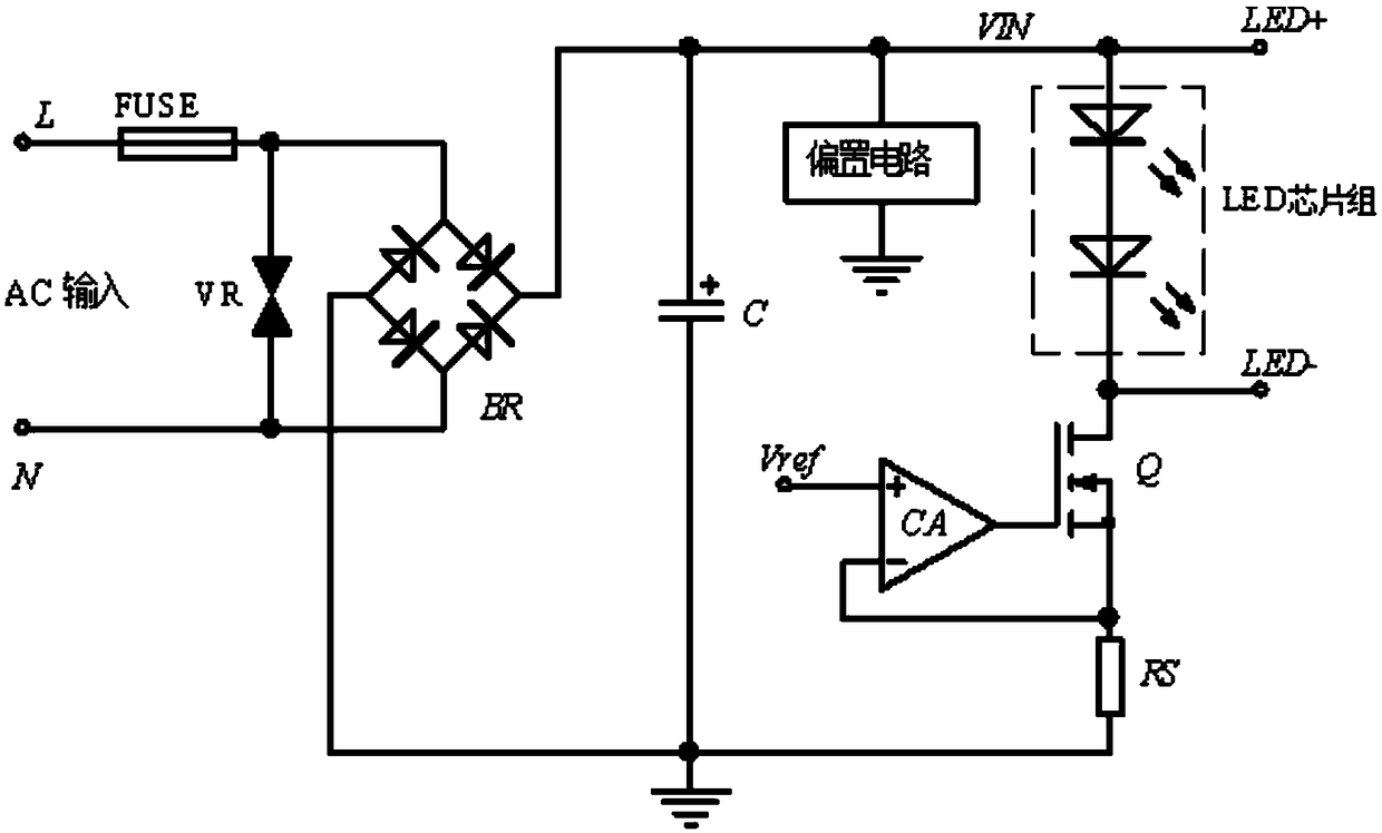
[0024] figure 2 It is a traditional small and medium power LED lighting circuit structure, with input protection circuit, bridge rectifier, constant current control circuit.

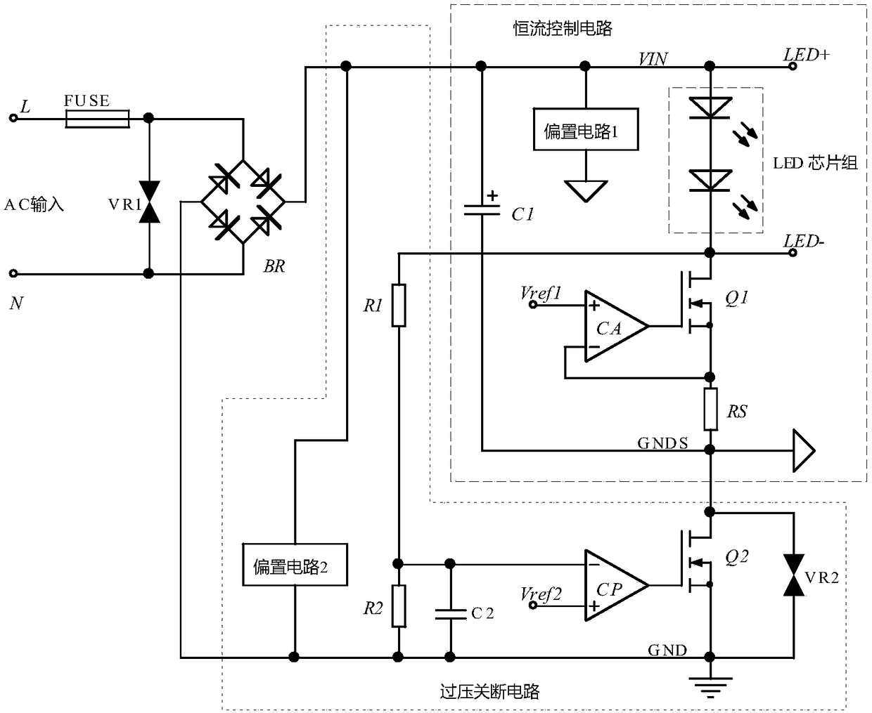
[0025] figure 1 The embodiment of the present invention is also a diagram for the abstract of the specification, including an input protection circuit, a bridge rectifier, a constant current control circuit, and an overvoltage shutdown circuit.

[0026] The constant current control circuit is composed of energy storage capacitor C1, series LED chipset, LED working current sampling resistor RS, current amplifier CA, reference voltage source, adjustment tube Q1 and bias circuit 1; the overvoltage shutdown The circuit is composed of the first voltage sampling resistor R1, the second voltage sampling resistor R2, the high-frequency filter capacitor C2, the comparator CP, the power switch tube Q2, the bias circuit 2, and the lightning protection device VR2; the input protection circuit consists of a fuse C...

Embodiment 2

[0038] In the following specific implementation process, it is assumed that in the 220V power supply state, in order to improve efficiency, the cut-off voltage V 2 Generally take (V F +30~40V), then the voltage V 2 Corresponding time:

[0039]

[0040] where U IN is the effective value of the input AC voltage, and f is the frequency of the AC voltage.

[0041] When the instantaneous value of the AC voltage is greater than the cut-off voltage V2, the switch tube Q2 is turned off, the energy storage capacitor C is discharged, and the terminal voltage V C Decrease, until the time t3, the voltage at the terminal C of the energy storage capacitor V C down to V 1 , to avoid flicker, obviously V 1 The minimum value is V F , then the capacity of the energy storage capacitor C.

[0042]

[0043] where P O is the output power of the lamp, and η is the efficiency of the driving power supply.

[0044] Assuming that the number of LED chips in series is 66, and the working v...


PUM


Abstract

The invention discloses a high-efficiency LED lighting lamp linear driving circuit. The circuit comprises four parts, including an input protection circuit, a bridge type rectifier, a constant currentcontrol circuit and an overvoltage shutdown circuit, wherein the constant current control circuit is similar to a conventional linear driving circuit of an LED lighting fixture, the overvoltage shutdown circuit is connected in series between a negative terminal of the constant current control circuit and a negative terminal of the rectifier bridge and is composed of an input voltage sampling circuit, a reference power source, a comparator CP and an N-channel power switch tube, the circuit is generally applicable to multiple types of small and medium power LED light source lighting fixtures, and the circuit has advantages of high luminous efficiency, small temperature rise of a constant current control tube, small current surge current, wide input voltage range and the like.

Description

technical field [0001] The invention relates to the field of LED lighting, in particular to a linear drive circuit for LED lighting fixtures with high light efficiency. Background technique [0002] LED light source has the advantages of environmental protection, energy saving, long service life, low driving voltage, etc., and is recognized as the most promising lighting source in the 21st century. Due to the limitation of cost, lamp size, EMI interference and other factors, in recent years, small and medium power LED lighting lamps, such as bulb lamps, light pipes, ceiling lamps, spotlights, etc., have mostly adopted linear drive methods. The traditional LED linear drive circuit with capacitor filter is mainly composed of insurance tube FUSE, varistor VR, bridge rectifier BR, filter capacitor C, series LED chipset, LED working current sampling resistor Rs, current amplifier CA, reference voltage source V ref , adjustment tube Q and bias circuit, etc., as attached figure 2...

Claims


Application Information

Patent Timeline
Patent Type & Authority Applications(China)
IPC IPC(8): H05B33/08H05B44/00
CPCH05B45/40H05B45/00Y02B20/30
Inventor 潘永雄蔡炳利陈林海李勇
Owner LETARON ELECTRONICS
Why Eureka
Try Eureka