
Display heat dissipation structure and heat dissipation method

A technology of heat dissipation structure and display, applied in the direction of instrument, electrical equipment structural parts, cooling/ventilation/heating transformation, etc., can solve the problem of burnout of display, achieve the effect of improving efficiency and solving heat dissipation

Active Publication Date: 2018-12-07
JIANGMEN WEISHI SEMICON TECH CO LTD
View PDF3 Cites 0 Cited by
  • Summary
  • Abstract
  • Description
  • Claims
  • Application Information

AI Technical Summary

Problems solved by technology

[0004] The composition circuit of the display includes video amplification circuit, field scanning circuit, line scanning circuit, switching power supply, pattern recognition and control circuit. When these circuits work, they will release a lot of heat. If the heat stays inside the display for a long time, it will cause The display burns out, those skilled in the art hope to provide a kind of heat dissipation structure of the display that can effectively solve the heat dissipation problem

Method used


Image

  • Display heat dissipation structure and heat dissipation method
  • Display heat dissipation structure and heat dissipation method
  • Display heat dissipation structure and heat dissipation method

Examples


Embodiment 1

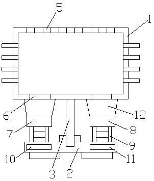
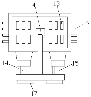
[0029] like Figure 1-2As shown, a heat dissipation structure of a display includes a housing 1 and a base 2, the base 2 is provided with a groove (not shown), the groove is provided with a support column 3, and the support column 3 is screwed into In the groove, the support column 3 is threadedly connected with the groove, and the back of the housing 1 is provided with an insertion part 4 that fits with the support column 3, and the insertion part 4 is fixedly connected with the back of the housing 1, and the support The column 3 is inserted into the insertion part 4, and the support column 3 is screwed to the insertion part 4. The top surface of the casing 1 is provided with cooling holes 5, and the cooling holes 5 are arranged at equal intervals. The bottom surface of the casing 1 Through-holes 6 are provided, and the through-holes 6 are symmetrically distributed. The first cooling fan 7 and the second cooling fan 8 are respectively arranged on the two sides of the base 2. ...

Embodiment 2

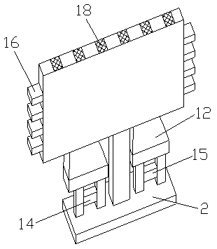
[0032] like Figure 1-3 As shown, a heat dissipation structure of a display includes a housing 1 and a base 2, the base 2 is provided with a groove (not shown), the groove is provided with a support column 3, and the support column 3 is screwed into In the groove, the support column 3 is threadedly connected with the groove, and the back of the housing 1 is provided with an insertion part 4 that fits with the support column 3, and the insertion part 4 is fixedly connected with the back of the housing 1, and the support The column 3 is inserted into the insertion part 4, and the support column 3 is screwed to the insertion part 4. The top surface of the casing 1 is provided with cooling holes 5, and the cooling holes 5 are arranged at equal intervals. The bottom surface of the casing 1 Through-holes 6 are provided, and the through-holes 6 are symmetrically distributed. The first cooling fan 7 and the second cooling fan 8 are respectively arranged on the two sides of the base 2....


PUM


Abstract

The invention discloses a display heat dissipation structure and heat dissipation method. The display heat dissipation structure includes a casing and a base, a groove is formed in the base, a supporting column is arranged on the groove, the supporting column is screwed into the groove, the supporting column is in threaded connection with the groove, an inserting part matched with the supporting column is arranged on the back surface of the casing, the inserting part is fixedly connected with the back surface of the casing, the supporting column is inserted into the inserting portion, the supporting column is in threaded connection with the inserting portion, and heat dissipation holes are formed in the top surface of the casing, the heat dissipation holes are distributed at equal intervals, and through holes are formed in the bottom surface of the casing, the through holes are symmetrically distributed, and a first cooling fan and a second cooling fan are arranged on the two sides ofthe upper surface of the base respectively, the first cooling fan and the second cooling fan are located under the through holes, supporting legs are arranged below the first cooling fan and the second cooling fan; the display heat dissipation structure can effectively solve the problem of heat dissipation.

Description

technical field [0001] The invention relates to a heat dissipation structure of a display and a heat dissipation method thereof. Background technique [0002] A display is also commonly referred to as a monitor. The display is an I / O device belonging to the computer, that is, an input and output device. It is a display tool that displays a certain electronic file on the screen through a specific transmission device and then reflects it to the human eye. [0003] According to different manufacturing materials, it can be divided into: cathode ray tube display (CRT), plasma display PDP, liquid crystal display LCD and so on. [0004] The composition circuit of the display includes video amplification circuit, field scanning circuit, line scanning circuit, switching power supply, pattern recognition and control circuit. When these circuits work, they will release a lot of heat. If the heat stays inside the display for a long time, it will cause The display burns out, and those...

Claims


Application Information

Patent Timeline
Patent Type & Authority Applications(China)
IPC IPC(8): H05K7/20G09F9/00
CPCG09F9/00H05K7/20972
Inventor 不公告发明人
Owner JIANGMEN WEISHI SEMICON TECH CO LTD
Learn More