Cutting method for solar-grade silicon wafer

A technology of solar-grade silicon wafer and cutting method, applied in the field of solar-grade silicon wafer cutting, can solve the problems of scrap and gap of silicon wafer, and achieve the effect of reducing edge gap, increasing contact length and avoiding damage

Active Publication Date: 2018-12-11
扬州宏祥光电科技有限公司
View PDF7 Cites 2 Cited by
  • Summary
  • Abstract
  • Description
  • Claims
  • Application Information

AI Technical Summary

Problems solved by technology

[0003] When cutting silicon wafers, since silicon wafers are hard and brittle materials, it is easy to cause gaps on the edges of silicon wafers during wire cutting, resulting in the scrapping of silicon wafers

Method used


Image

  • Cutting method for solar-grade silicon wafer
  • Cutting method for solar-grade silicon wafer
  • Cutting method for solar-grade silicon wafer

Examples


Embodiment Construction

[0029] In order to make the technical means, creative features, goals and effects achieved by the present invention easy to understand, the present invention will be further described below in conjunction with specific embodiments.

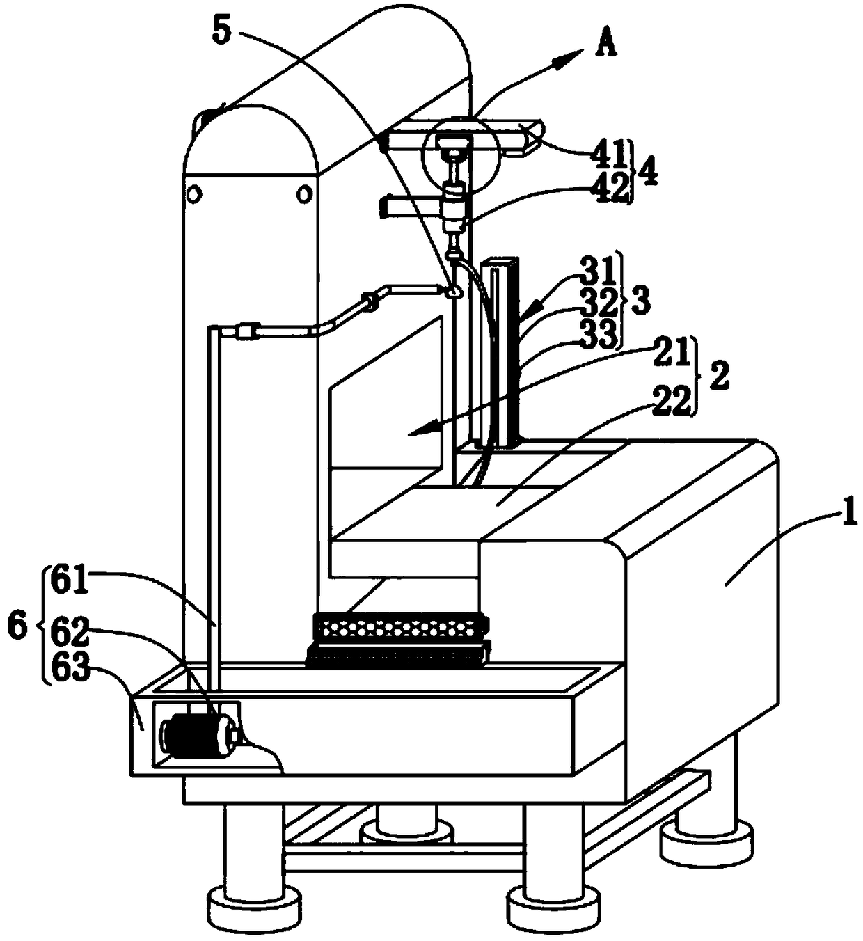
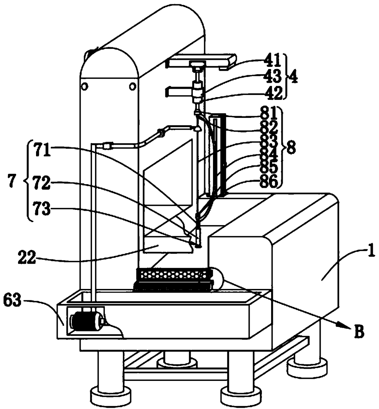
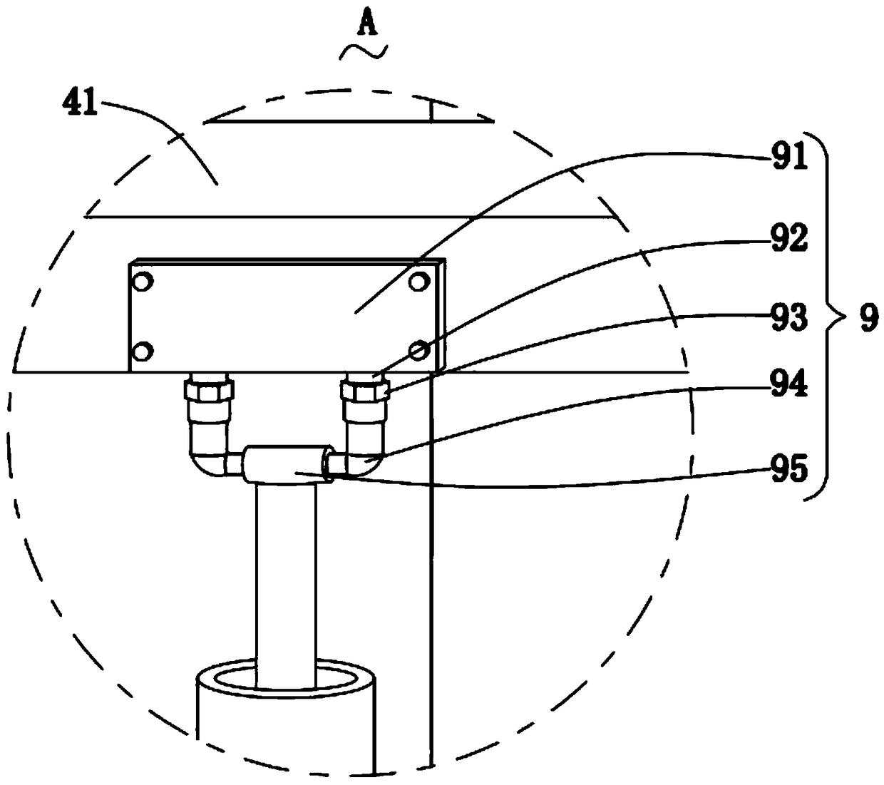
[0030] like figure 1 , figure 2 , image 3 and Figure 5 Shown, a kind of solar grade silicon chip cutting method of the present invention, this method comprises the following steps:

[0031] S1, electroplating a layer of metal film on the surface of the silicon wafer by electroplating;

[0032] S2, put the electroplated silicon wafer in S1 into the wire cutting equipment and cut it into pieces, and at the same time of wire cutting, use the silicon wafer as the anode, the carbon rod as the cathode, and the electroplating solution as the cutting fluid, and cut while electroplating;

[0033] S3, putting the silicon wafer cut in S2 into a pickling pool, and washing off the metal film on the surface of the silicon wafer;

[0034]The wire cutting...


PUM


Abstract

The invention relates to the technical field of silicon wafer production, in particular to a cutting method for a solar-grade silicon wafer. The method comprises the following steps: S1, electroplating the surface of the silicon wafer with a layer of metal film by means of electroplating; S2, placing the silicon wafer electroplated in S1 into linear cutting equipment and cutting the silicon waferinto slices, and during linear cutting, taking the silicon wafer as an anode, taking a carbon rod as a cathode, taking an electroplating liquid as a cutting liquid, and cutting while electroplating; and S3, placing the silicon wafer cut in S2 into an acid pickling tank, and cleaning away the metal film on the surface of the silicon wafer. According to the method, the surface of the silicon wafer to be cut is plated with the layer of metal film, so that the generation of edge notches of the silicon wafer can be reduced.

Description

technical field [0001] The invention relates to the technical field of silicon wafer production, in particular to a solar-grade silicon wafer cutting method. Background technique [0002] The diamond wire cutting machine adopts the way of unidirectional circulation or reciprocating circulation of the diamond wire, so that the diamond wire and the object to be cut form a relative grinding motion, so as to achieve the purpose of cutting; the cutting principle of the diamond wire cutting machine is similar to that of a bow saw. The high-speed rotating and reciprocating winding drum drives the diamond wire to reciprocate. The diamond wire is tensioned by two tensioning wire wheels (spring or pneumatic), and two guide wheels are added to ensure cutting accuracy and surface shape. [0003] When cutting the silicon wafer, since the silicon wafer is a hard and brittle material, it is easy to cause cracks on the edge of the silicon wafer during wire cutting, resulting in the scrappin...

Claims


Application Information

Patent Timeline
Patent Type & Authority Applications(China)
IPC IPC(8): B28D5/04B28D7/02B28D7/00
CPCB28D5/0058B28D5/0076B28D5/045
Inventor 兰凤
Owner 扬州宏祥光电科技有限公司
Why Eureka
Try Eureka