
Tray welding assembly line

A welding line and tray technology, applied in the field of plastic tray hot plate welding line equipment, can solve the problems of precise positioning and fine processing of difficult injection molding products, unfavorable production scale of enterprises, low processing efficiency, etc., to achieve outstanding work efficiency, ideal control ability, The effect of improving processing efficiency

Pending Publication Date: 2018-12-11
SUZHOU KEBER PRECISION MACHINERY
View PDF9 Cites 4 Cited by
  • Summary
  • Abstract
  • Description
  • Claims
  • Application Information

AI Technical Summary

Problems solved by technology

[0002] At present, for injection molded products that need to be welded and assembled after injection molding, it is difficult to achieve precise positioning of injection molded products and fine processing after welding by traditional techniques. Using manual multi-process processing methods can effectively complete product welding, flash removal, Slitting and other processing
However, there are many potential safety hazards in manual operation, and the processing efficiency is relatively low.
Some independent processing equipment, such as hot-melt welding machines, etc., only have the processing of a single process. During operation, they also need to put the workpiece into the next operating equipment to connect to the second process through artificial transportation, although to a certain extent The work efficiency has been improved, but under the macro management mode, the degree of automation is low, and the energy consumption of the equipment is also increased, which is not conducive to the expansion of the production scale of the enterprise.

Method used


Image

  • Tray welding assembly line
  • Tray welding assembly line
  • Tray welding assembly line

Examples


Embodiment Construction

[0036] The preferred embodiments of the present invention will be described in detail below in conjunction with the accompanying drawings, so that the advantages and features of the present invention can be more easily understood by those skilled in the art, so as to define the protection scope of the present invention more clearly.

[0037] Please refer to the attached Figures 1 to 13 , the embodiment of the present invention includes:

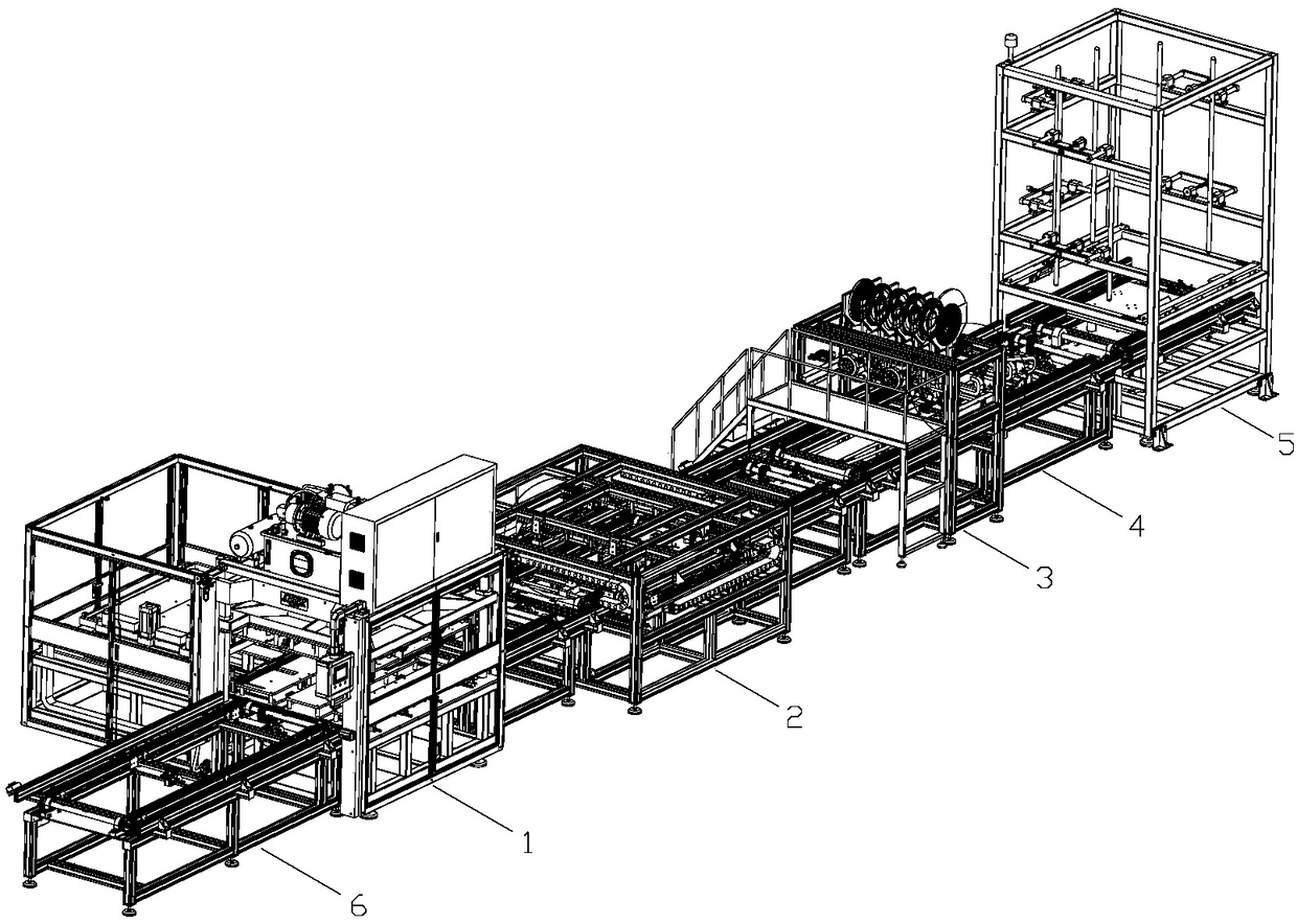
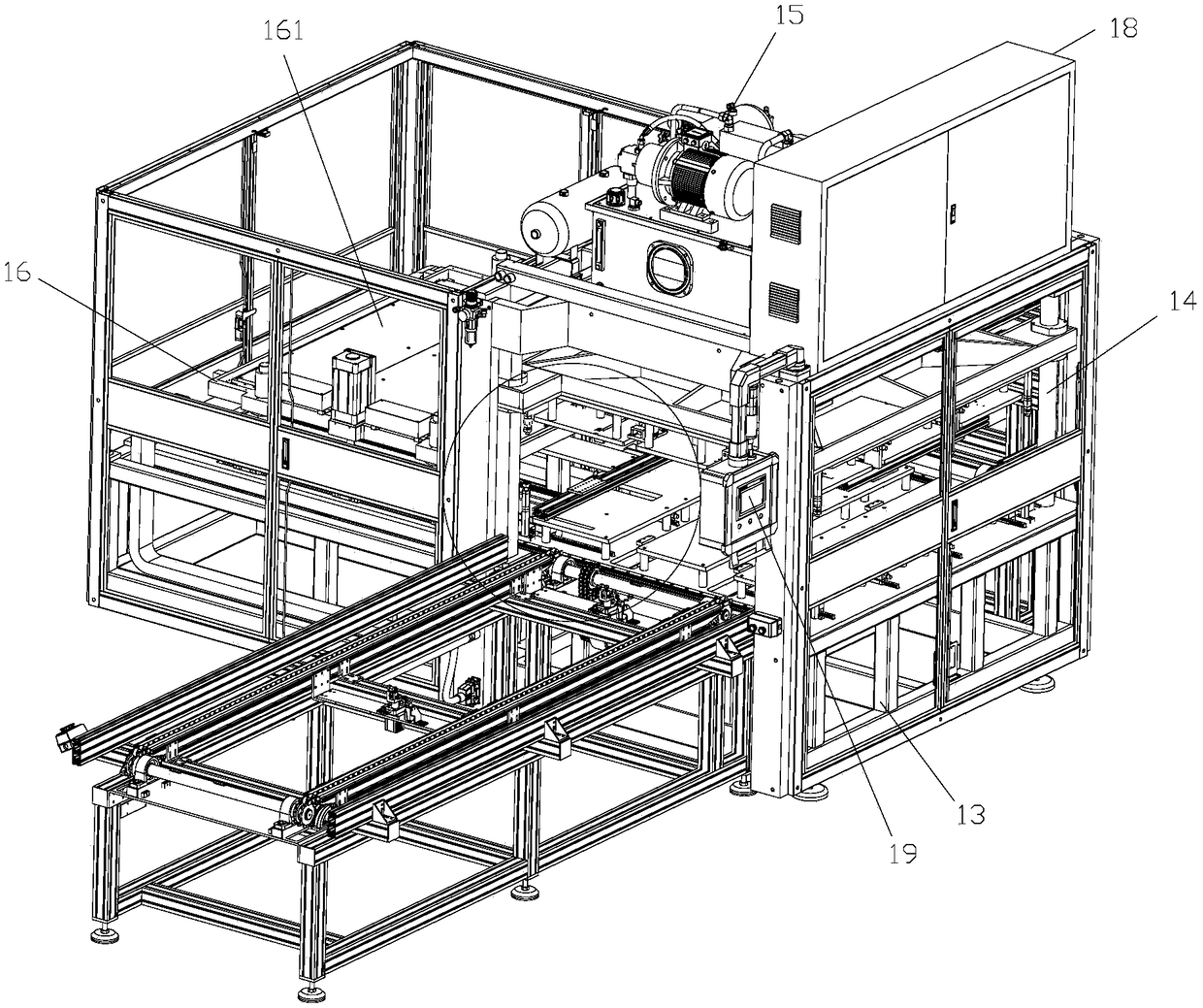
[0038] A pallet welding assembly line is provided in sequence: a material sending station, a hot plate welding station, an edge milling station, a hot air welding station, a cutting station and a discharging station. Plastic trays pass through these stations in turn, and are processed accordingly at these stations, automatically controlling the processing process of products from raw materials to finished products.

[0039] A material delivery device 6 is arranged on the material delivery station, and the material delivery device 6 includes...


PUM


Abstract

The invention discloses a tray welding assembly line, and relates to the field of heat plate welding assembly line equipment for plastic trays. The tray welding assembly line is sequentially providedwith a material distribution working station, a heat plate welding working station, an edge milling working station, a hot air welding working station, a splitting working station and a material discharge working station; after the tray raw material is welded by a heat plate, the tray is sent into a second chain group to perform edge milling, and a milling knife is used for treating the spilled material at the welding edge of the tray; then, the tray is sent into a third chain group to perform hot air welding on antislip strips, and a hot air gun is used for performing heat melting welding onthe crossing part of the antislip and the tray; after the welding is completed, the synchronous splitting is performed; finally, the single tray after splitting is sent into the material discharge working station on a fourth chain group, and the trays are sequentially stacked up; after ten trays are overlapped, the trays are fetched out and delivered out by an operator. The tray welding assembly line has the advantages that the automation degree is high; a plurality of processing structures are integrated into one assembly line; on the basis of heat melting welding of the plastic tray, each procedure is performed on the sustained running material delivery line, and the working efficiency of the tray welding assembly line is outstanding.

Description

technical field [0001] The invention relates to the field of plastic pallet hot plate welding assembly line equipment, in particular to a pallet welding assembly line. Background technique [0002] At present, for injection molded products that need to be welded and assembled after injection molding, it is difficult to achieve precise positioning of injection molded products and fine processing after welding by traditional techniques. Using manual multi-process processing methods can effectively complete product welding, flash removal, Slitting and so on. However, there are many potential safety hazards due to manual operation, and the processing efficiency is relatively low. Some independent processing equipment, such as hot-melt welding machines, etc., only have the processing of a single process. During operation, they also need to put the workpiece into the next operating equipment to connect to the second process through artificial transportation, although to a certain...

Claims


Application Information

Patent Timeline
Patent Type & Authority Applications(China)
IPC IPC(8): B29C65/72B29C65/78
CPCB29C65/72B29C65/78
Inventor 文华波王卜
Owner SUZHOU KEBER PRECISION MACHINERY
Learn More