
Railway switch wayside control device and method

A control device and technology of switch rails, which are applied in railway signals, railway car body components, railway signals and safety, etc., can solve the problems of high-precision data of the switch machine, abnormal malfunction of the outdoor switch machine, increase the daily Maintenance workload and other issues, to achieve the effect of facilitating daily maintenance work, improving high-precision data collection and monitoring, and reducing construction workload and project cost

Inactive Publication Date: 2018-12-11
LANZHOU JIAOTONG UNIV
View PDF8 Cites 12 Cited by
  • Summary
  • Abstract
  • Description
  • Claims
  • Application Information

AI Technical Summary

Problems solved by technology

[0003] Most of the existing railway signal control adopts a centralized control method, that is, the control computer and the underlying control logic combination circuit and acquisition circuit are all placed indoors, and a large number of signal cables are used to connect the indoor turnout control logic combination circuit with the outdoor DC or DC. For the connection of AC switch point machine equipment, since the distribution of outdoor switch point machines is relatively scattered and far away, the signal cable is affected by external interference signals when the control distance is long, and there is an interlocking device in the control center to control and monitor the outdoor switch point machines in real time Insufficient, in extreme cases, it may even lead to safety hazards of abnormal misoperation of the outdoor turnout switch machine, which is not conducive to the high-precision data collection and monitoring of the turnout switch machine, and also increases the daily maintenance workload. Problems such as high project cost

Method used


Image

  • Railway switch wayside control device and method
  • Railway switch wayside control device and method

Examples


Embodiment Construction

[0038] The preferred embodiments of the present invention will be described below in conjunction with the accompanying drawings. It should be understood that the preferred embodiments described here are only used to illustrate and explain the present invention, and are not intended to limit the present invention.

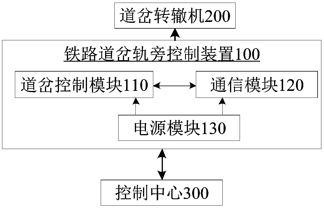
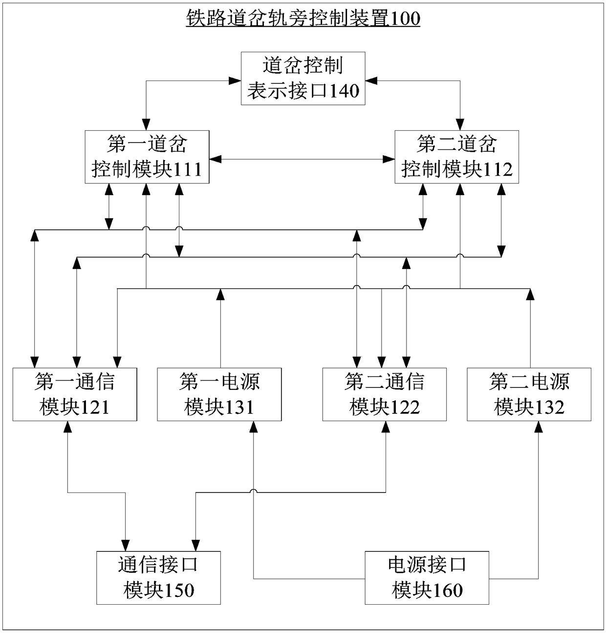
[0039] Aiming at the inaccurate real-time control and monitoring of the outdoor switch switch machine by the existing interlocking equipment of the control center, the present invention places a trackside control device beside the track of the station, preferably, a trackside control device is placed beside the track in the throat area of ​​the station The device monitors and collects the state of the switch machine in real time through the switch control module in the trackside control device, and sends the monitored and collected information to the control center through the communication module, and the communication module sends the control center to the The effe...


PUM


Abstract

The invention discloses a railway switch wayside control device and a railway switch wayside control method, wherein, the railway switch wayside control device is arranged beside the track and comprises a switch control module, a communication module and a power module; The turnout control module is used for connecting with the turnout switch machine, controlling the turnout switch machine and monitoring the state of the turnout switch machine. The communication module is electrically connected with the switch control module, and is used for sending out the state of the switch machine monitored by the switch control module, receiving control information, and transmitting the received control information to the switch control module. The power supply module provides power for the switch control module and the communication module. The switch control module controls the switch machine according to the control information. Therefore, the problem of real-time control and monitoring of switch machine caused by external disturbance signal of signal cable with long control distance is solved.

Description

technical field [0001] The invention relates to the field of railway signal control, in particular to a trackside control device and method for railway turnouts. Background technique [0002] At present, with the rapid development of railway transportation and urban rail transit, a large number of DC or AC switch machine equipment are used. For the safety control and status monitoring of the signal infrastructure equipment, different numbers of safety equipment are used. The type relay constitutes a control logic combination circuit or a state acquisition circuit to realize the control and monitoring of the switch machine. [0003] Most of the existing railway signal control adopts a centralized control method, that is, the control computer and the underlying control logic combination circuit and acquisition circuit are all placed indoors, and a large number of signal cables are used to connect the indoor turnout control logic combination circuit with the outdoor DC or DC. ...

Claims


Application Information

Patent Timeline
Patent Type & Authority Applications(China)
IPC IPC(8): B61L7/06B61L7/08
CPCB61L7/067B61L7/08
Inventor 陈光武杨菊花邢东峰石建强李鹏司涌波梁豆豆
Owner LANZHOU JIAOTONG UNIV
Learn More