Prefabricated reinforced concrete shear wall and construction method

A reinforced concrete and shear wall technology, applied in walls, building components, buildings, etc., can solve problems such as poor connection of vertical steel bars, difficulty in ensuring the quality of joint parts, and unfavorable seismic resistance of structures, so as to solve the problems of stress and construction problems, good connection effect, good mechanical properties and seismic performance

Active Publication Date: 2018-12-11
SHANDONG UNIV OF SCI & TECH
View PDF5 Cites 6 Cited by
  • Summary
  • Abstract
  • Description
  • Claims
  • Application Information

AI Technical Summary

Problems solved by technology

Reinforced concrete shear walls are generally prefabricated by floor, that is, the wall between the upper and lower floors is prefabricated as a unit, and the prefabricated components are split at the junction of the floor and the shear wall. Therefore, the quality of the joints is difficult to guarantee. The earthquake resistance of the structure is not good
The vertical connection between two prefabricated shear walls mainly depends on grouting materials, and the vertical reinforcement is not well connected, which affects its tensile performance
The on-site construction of prefabricated reinforced concrete shear walls is relatively difficult. There are many vertical steel bars in the shear walls. Due to manufacturing errors, transportation deformation, vibration displacement and other reasons, the vertical steel bars will be dislocated to a certain extent, and it is not easy to insert them into the connection. In the sleeve, the construction is more difficult

Method used


Image

  • Prefabricated reinforced concrete shear wall and construction method
  • Prefabricated reinforced concrete shear wall and construction method
  • Prefabricated reinforced concrete shear wall and construction method

Examples


Embodiment Construction

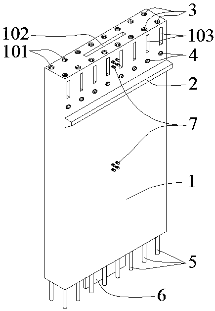
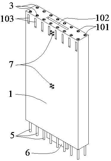
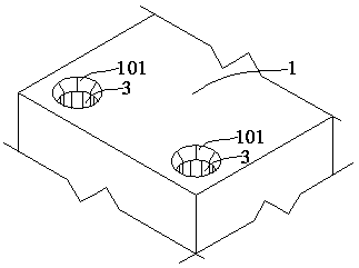
[0019] like Figure 1-Figure 3 As shown, a prefabricated reinforced concrete shear wall consists of wall panels (1), corbels (2), sleeves (3), sleeves (4), insert bars (5), steel plates (6) and anchor bolts (7) composition; the corbel (2) is located on the side of the wallboard (1), and the top surface of the corbel (2) is not less than 600 mm from the top surface of the wallboard (1); the sleeve (3) is embedded in the wallboard ( 1), the top surface of the sleeve (3) is 10mm away from the top surface of the wallboard (1), the upper part of the sleeve (3) is the horn hole (101) of the wallboard (1), and the sleeve (3) has two rows ;The casing (4) is pre-buried on the side of the wallboard (1), the casing (4) and the corbel (2) are on the same side of the wallboard (1), and the position of the casing (4) is higher than the corbel The position of (2), the distance from the top surface of the corbel (2) to the center of the casing (4) is determined according to the thickness of ...


PUM


Abstract

The invention relates to a prefabricated reinforced concrete shear wall and a construction method. The shear wall comprises a wall board, a bracket, sleeves, casing pipes, joint bars, a steel plate and anchor bolts and is characterized in that the bracket is located on the lateral side of the wall board, the sleeves are pre-embedded into the upper portion of the wall board, the casing pipes are pre-embedded into the lateral side of the wall board, the joint bars and the steel plate extend out from the bottom surface of the wall board, and the anchor bolts are pre-embedded into two lateral sides of the wall board; each sleeve comprises an outer tube, a pressing piece and bolts, the upper portion of each sleeve is in squeezing connection with one joint bar, and the lower portion of each sleeve is connected with one joint bar in a threaded and sleeved manner. During construction, downward pressure is applied through supports to allow two walls to contact tightly, and bolts on the sleevesare screwed to clamp the joint bars to achieve squeezing connection. The prefabricated reinforced concrete shear wall has the advantages that the stress and construction problems of the prefabricatedreinforced concrete shear wall can be solved, node areas are good in stress performance and seismic performance, firm vertical reinforcing bar connection is achieved, and the shear wall is easy to construct.

Description

technical field [0001] The invention relates to the field of prefabricated shear walls in assembled reinforced concrete structures. Background technique [0002] At present, prefabricated structures are widely used, and shear walls are important components of high-rise buildings, and their prefabrication level affects the prefabrication level of the entire structure. The existing prefabricated reinforced concrete shear walls have certain problems in terms of structure, stress and construction. Reinforced concrete shear walls are generally prefabricated by floor, that is, the wall between the upper and lower floors is prefabricated as a unit, and the prefabricated components are split at the junction of the floor and the shear wall. Therefore, the quality of the joints is difficult to guarantee. The earthquake resistance of the structure is unfavorable. The vertical connection between two prefabricated shear walls mainly depends on grouting materials, and the vertical reinf...

Claims


Application Information

Patent Timeline
Patent Type & Authority Applications(China)
IPC IPC(8): E04B2/56
CPCE04B2/56
Inventor 丛术平张征韩金生王来王清
Owner SHANDONG UNIV OF SCI & TECH
Why Eureka
Try Eureka