
Support system, assembly-type laminated frame column and column bottom module erecting method

A support system and assembled technology, applied in the direction of pillars, columns, pier columns, etc., can solve the problems of affecting the appearance quality of laminated frame columns, high cost, and unreliable node connections

Pending Publication Date: 2018-12-11
SANY CONSTR TECH CO LTD
View PDF0 Cites 3 Cited by
  • Summary
  • Abstract
  • Description
  • Claims
  • Application Information

AI Technical Summary

Problems solved by technology

The existing prefabricated frame-column joints have complex stress forms, uneven stiffness distribution, unreliable joint connections, and structural safety is not easy to guarantee. This will become a key issue restricting the development of prefabricated buildings.
[0003] Currently, there are generally three types of frame columns: one is the traditional cast-in-place frame column, which is reliable in joint connection, but has low labor efficiency, poor environmental protection and high cost
One is fully prefabricated concrete frame columns, which are mass-produced in factories and greatly improve operating efficiency, but the joint connection technology is immature and the on-site installation cost is relatively high
There is also a prefabricated laminated frame column, which can improve work efficiency and reduce costs. However, it is difficult to control the molding quality of the cast-in-place concrete at the bottom of the laminated frame column. If it is not handled properly, it will seriously affect the quality of the laminated frame column. Appearance Quality

Method used


Image

  • Support system, assembly-type laminated frame column and column bottom module erecting method
  • Support system, assembly-type laminated frame column and column bottom module erecting method
  • Support system, assembly-type laminated frame column and column bottom module erecting method

Examples


Embodiment 1

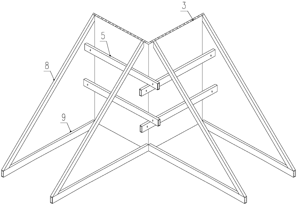
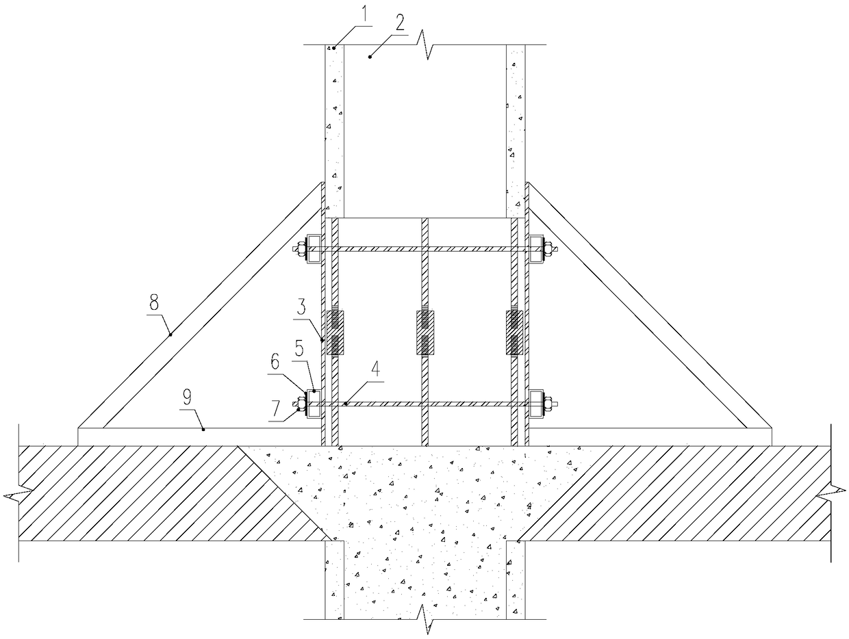
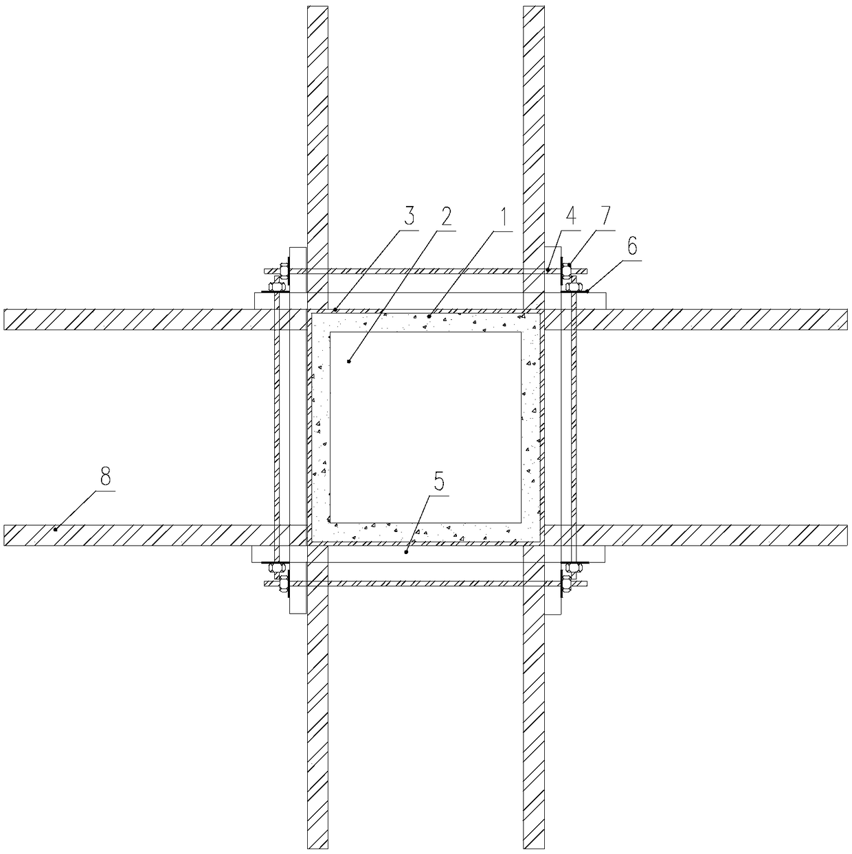
[0042] An embodiment of the present invention provides a support system, the support system includes four support units, and the four support units surround the bottom of the prefabricated laminated column;

[0043] Each of the supporting units includes a steel formwork 3, a square steel pipe horizontal sub-keel 5, and an L-shaped support assembly A; wherein the steel formwork 3 is set in a vertical state; the square steel pipe horizontal sub-keel 5 is arranged along the horizontal Fixedly connected on the surface of the steel formwork 3; the L-shaped support assembly A is in the shape of "∠", the upper end of the right side of the L-shaped support assembly A is connected to the top of the steel formwork 3, and the L-shaped support assembly A The lower end on the right side of the L-shaped support assembly A is correspondingly connected to the bottom of the steel formwork 3, and the bottom edge of the L-shaped support assembly A is connected to the ground.

[0044] Analysis of...


PUM


Abstract

The invention discloses a support system, an assembly-type laminated frame column and a column bottom module erecting method. The support system comprises four support units which surround around fourcorners of a column bottom of the laminated frame column. Each support unit comprises a steel template, a square steel tube horizontal sub-keel and an L-shaped support assembly. Steel templates are arranged in the vertical state. Square steel tube horizontal sub-keels are fixedly connected to surfaces of the steel templates along the horizontal directions. L-shaped support assemblies are in the shapes of L. The assembly-type laminated frame column and the column bottom module erecting method relate to the above support system. The support system, the assembly-type laminated frame column and the column bottom module erecting method have stable and reliable erecting effect. Meanwhile, construction cost is markedly reduced. High promotion and application value are acquired.

Description

technical field [0001] The invention relates to the technical field of prefabricated building accessories, in particular to a supporting system, a prefabricated superimposed frame column and a supporting method for a column bottom module. Background technique [0002] As the country pays more and more attention to the development of prefabricated buildings, the development of prefabricated buildings is getting better and better. Among them, the prefabricated laminated frame-column structure is a structural form that is receiving more and more attention in the application of residential buildings. The prefabricated composite frame column structure absorbs the advantages of cast-in-place concrete structure and prefabricated concrete structure, and has good overall performance. Reinforced concrete frame columns as vertical load-bearing members are the main load-bearing and force-transmitting members of concrete structures, and their integrity and seismic performance are the de...

Claims


Application Information

Patent Timeline
IPC IPC(8): E04G13/02E04C3/34
CPCE04C3/34E04G13/02
Inventor 曹计栓王洪强孙伯禹李伟马荣全
Owner SANY CONSTR TECH CO LTD
Learn More