
An air amplifier for electric vehicles

A technology for air amplifiers and electric vehicles, which is applied to wind engines, engines, and wind power generation in the same direction as the wind. It can solve the problem of poor speed-up and guiding capabilities of air amplifiers, which affect the smooth development of electric vehicle design, and the volume and size of air amplifiers. Problems such as large structure, to achieve the effect of compact structure, improved stability and reliability, and simple structure

Inactive Publication Date: 2019-07-30
李素梅 +2
View PDF10 Cites 0 Cited by
  • Summary
  • Abstract
  • Description
  • Claims
  • Application Information

AI Technical Summary

Problems solved by technology

[0002] At present, in the electric vehicle equipment, in order to improve the power performance and endurance of the electric vehicle during operation and achieve the purpose of reducing wind noise, etc., a wind power generation system is installed in the electric vehicle, and the air flowing through the surface of the electric vehicle is used to generate electricity. Air flow rectification achieves the purpose of reducing wind resistance, but it is found during operation that because the current wind power equipment used for electric vehicles needs to maintain a continuous and stable wind speed and wind pressure during operation, the wind speed and wind pressure flowing through the vehicle surface are stable when the vehicle is running. The performance is relatively poor, so at present it is mainly to add air amplifiers to wind power generation equipment to increase the constant wind speed and wind pressure to meet the needs of power generation, but the air amplifiers currently used are often used in other industries. Therefore, on the one hand The size and structure of the air amplifier are relatively large, which cannot effectively meet the requirements for the use of electric vehicles with different structures. At the same time, it is easy to cause changes in the overall aerodynamic layout of the electric vehicle equipment, which seriously affects the smooth development of the design and use of electric vehicles. On the one hand, the air amplifiers currently used in electric vehicles cannot flexibly adjust the structure according to the needs of vehicle operation, resulting in relatively poor air amplifiers’ ability to pressurize, speed up and guide airflow, and cannot effectively meet the needs of electric vehicles. needs

Method used


Image

  • An air amplifier for electric vehicles

Examples


Embodiment Construction

[0015] In order to make the technical means, creative features, goals and effects achieved by the present invention easy to understand, the present invention will be further described below in conjunction with specific embodiments.

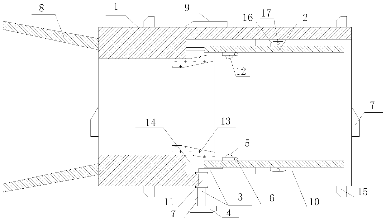
[0016] Such as figure 1 The air amplifier for an electric vehicle comprises a shroud 1, a reverse flow lining pipe 2, a drainage branch pipe 3, a drainage fan 4, a spray port 5, an angle sensor 6, a wind speed sensor 7, a shroud 8 and a control circuit 9. The deflector 1 is covered outside the reverse flow liner 2, and the deflector 1 and the reverse flow liner 2 are coaxially distributed, and the reverse flow liner 2 and the deflector 1 are slidably connected to each other through the guide rail 10 , the front end of the reverse flow liner 2 is located in the nozzle 1 and the distance between it and the front end of the nozzle 1 is not less than 5-10 cm, and not greater than 1 / 2 of the effective length of the nozzle 1, the reverse flow liner 2 T...


PUM


Abstract

The invention relates to an air amplifier for electric vehicles. The air amplifier comprises a guide hood, a backflow liner tube, diversion branch pipes, a diversion fan, spray ports, angle sensors, an air speed sensor, a diversion hood and a control circuit. The guide hood covers the backflow liner tube; the diversion hood is connected with the front end face of the guide hood; the sidewall of the guide hood is communicated with the tail end of the diversion branch pipe via a guide port; the front end face of one diversion branch pipe is communicated with the diversion fan; the front end of at least one another diversion branch pipe is communicated with the spray port; the spray ports are distributed evenly in the inner surface of the backflow liner tube around the axis of the backflow liner tube; each turnplate mechanism is provided with at least one angle sensor. The air amplifier has the advantages that the requirement on installation and use of different types of electric vehiclescan be effectively met; natural air flow can be effectively increased to carry out pressurizing and accelerating.

Description

technical field [0001] The invention relates to an electric vehicle equipment, in particular to an air amplifier for the electric vehicle. Background technique [0002] At present, in the electric vehicle equipment, in order to improve the power performance and endurance of the electric vehicle during operation and achieve the purpose of reducing wind noise, etc., a wind power generation system is installed in the electric vehicle, and the air flowing through the surface of the electric vehicle is used to generate electricity. Air flow rectification achieves the purpose of reducing wind resistance, but it is found during operation that because the current wind power equipment used for electric vehicles needs to maintain a continuous and stable wind speed and wind pressure during operation, the wind speed and wind pressure flowing through the vehicle surface are stable when the vehicle is running. The performance is relatively poor, so at present it is mainly to add air ampli...

Claims


Application Information

Patent Timeline
Patent Type & Authority Patents(China)
IPC IPC(8): F03D1/04F03D9/32F03D7/02
CPCF03D1/04F03D7/02F03D9/32Y02E10/72Y02E10/728
Inventor 李素梅李艳刘琦
Owner 李素梅
Learn More