Device and method for measuring main shaft rotation error by using circular gratings and autocollimators

A technology of autocollimator and rotation error, which is applied in the direction of measuring devices, optical devices, instruments, etc., can solve the problems of probe wear, affecting measurement accuracy, and shaft surface processing accuracy, so as to eliminate the impact and achieve high precision. The effect of precision positioning

Active Publication Date: 2018-12-11
DALIAN UNIV OF TECH
View PDF4 Cites 15 Cited by
  • Summary
  • Abstract
  • Description
  • Claims
  • Application Information

AI Technical Summary

Problems solved by technology

[0003] The existing high-precision spindle radial rotation error measurement methods mostly use the error separation method, the measurement and calculation process is complex, and most of them use contact displacement sensors, which are greatly affected by the machining accuracy of the shaft surface, and long-term measurement will lead to wear of the probe , affecting the measurement accuracy

Method used


Image

  • Device and method for measuring main shaft rotation error by using circular gratings and autocollimators
  • Device and method for measuring main shaft rotation error by using circular gratings and autocollimators
  • Device and method for measuring main shaft rotation error by using circular gratings and autocollimators

Examples


Embodiment Construction

[0028] The technical solution of the present invention will be described in detail below in conjunction with the accompanying drawings and specific embodiments.

[0029] Step 1, calibrate the installation error:

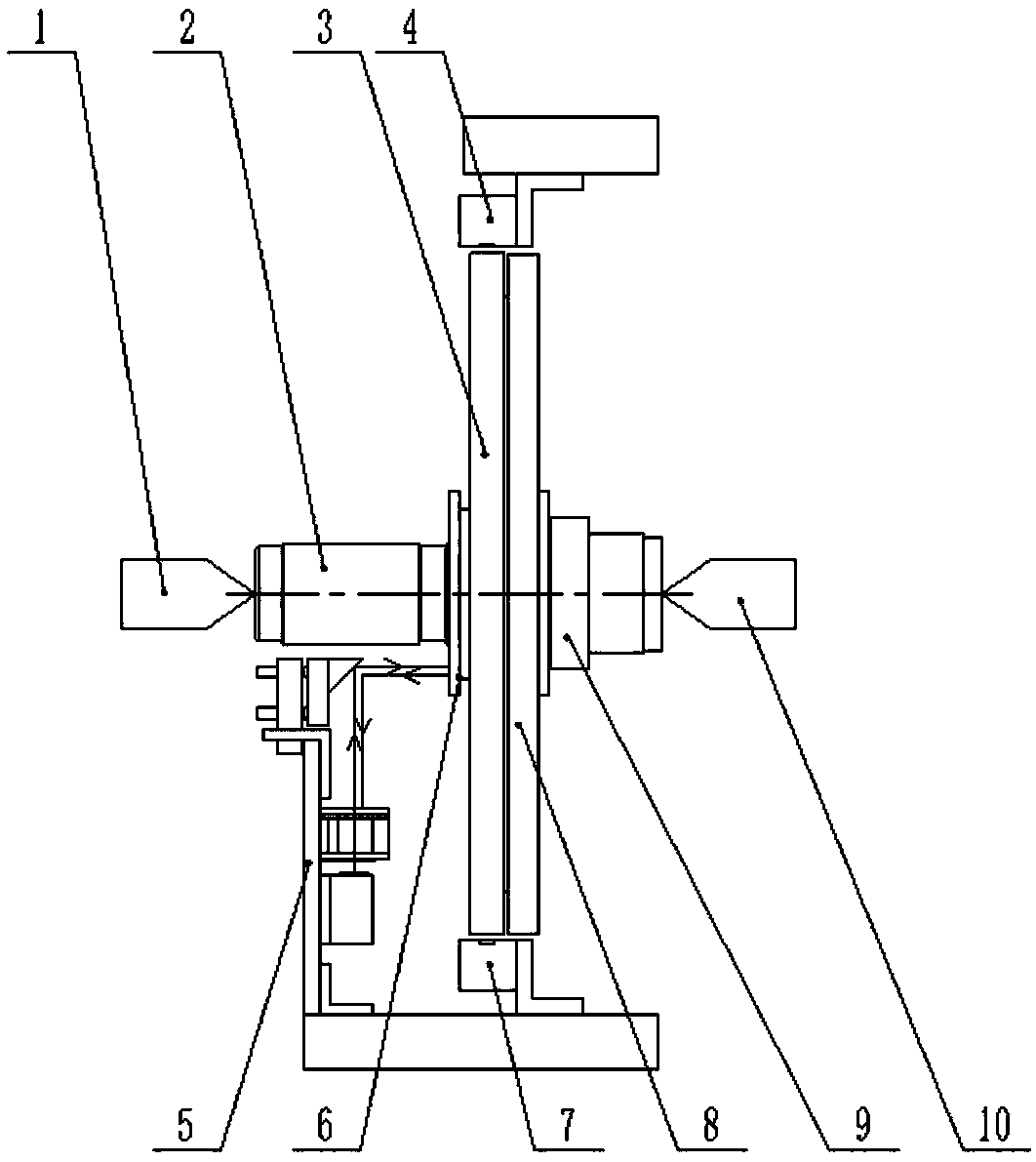
[0030] Step 1-1: If figure 1 As shown, the circular grating 3 is fixed on the flange 8, and then it is fixed as a whole on the right shoulder of the main shaft 2; an annular flat mirror 6 is pasted on the left shoulder of the main shaft 2.

[0031] Step 1-2: Fix the main shaft 2 with the grating and plane mirror installed with the top A1 and the top B10.

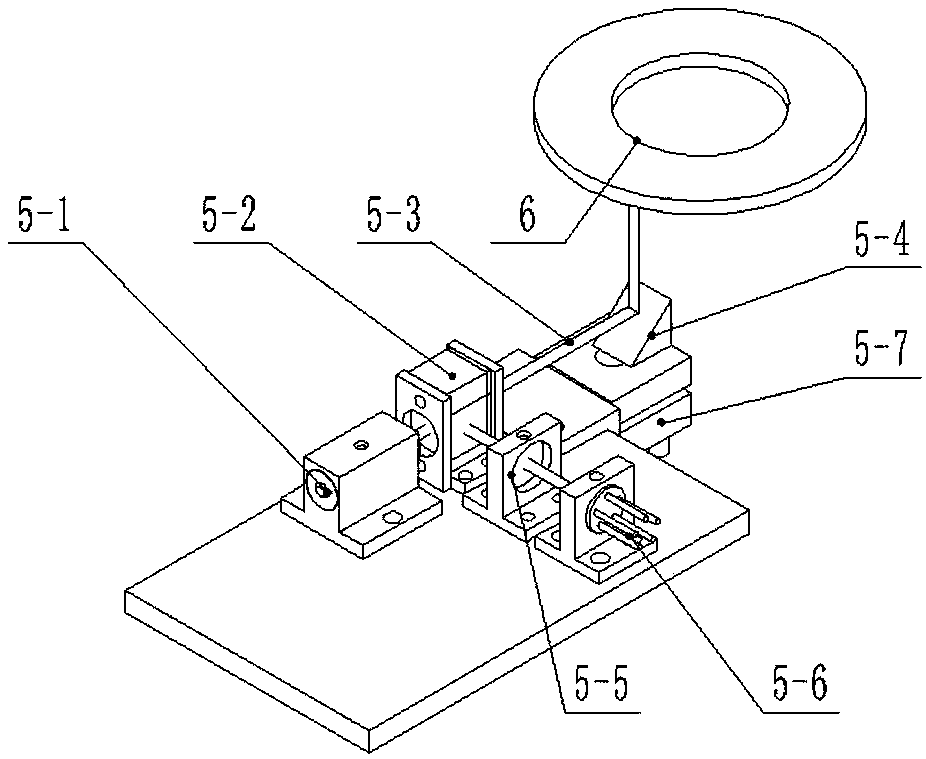
[0032] Step 1-3: Install the grating reading heads A4 and B7 on both sides of the circular grating; fix the autocollimator 5 on the left side of the main shaft 2, make the axis of the laser 5-1 parallel to the line connecting the two reading heads, and The light 5-3 hits the annular plane mirror 6 after being reflected by the right-angle mirror 5-4.

[0033] Step 1-4: Starting from the zero position of the grati...


PUM


Abstract

The invention belongs to the precision mechanical error field and displays a device and a method for measuring a main shaft rotation error by using circular gratings and autocollimators. The measuringdevice is formed by a set of double reading head circular gratings installed on a main shaft, a plane mirror attached to a shaft bottom end and a set of self-made autocollimators. When the main shafthas a radial rotation error, a radial motion error measured by the circular gratings and a deflection error measured by the autocollimators are combined to calculate the radial rotation error at anypoint on the shaft, and then, the motion state of the shaft during a rotation process is analyzed. By using the structure of the invention, the influences of a main shaft circularity, surface roughness and the changes of a load on the main shaft on a measurement result can be eliminated. And simultaneously, the device can be used to realize the high precision positioning of a main shaft rotation angle.

Description

technical field [0001] The invention belongs to the field of precision mechanical error measurement, and in particular relates to a device and method for measuring and calculating the radial rotation error of a main shaft by using a double-reading head circular grating and an autocollimator. Background technique [0002] Spindle rotation error refers to the deviation of the actual axis of rotation relative to the theoretical axis of rotation when the spindle rotates. Spindle rotation error mainly includes three forms: radial motion error, inclination swing error and axial movement error. Among them, the radial motion error and the inclination swing error are collectively called the spindle radial rotation error, which is the main reason affecting the machining error. [0003] The existing high-precision spindle radial rotation error measurement methods mostly use the error separation method, the measurement and calculation process is complex, and most of them use contact di...

Claims


Application Information

Patent Timeline
Patent Type & Authority Applications(China)
IPC IPC(8): G01B11/27G01B11/26
CPCG01B11/26G01B11/272
Inventor 娄志峰郝秀朋范光照
Owner DALIAN UNIV OF TECH
Why Eureka
Try Eureka