Unmanned vehicle semantic map modeling and application constructing method based on perception and location monitoring

A technology of semantic maps and modeling methods, applied in directions such as road network navigators, can solve the problems of not using the correlation of map elements, not making good use of the correlation of map elements, and lack of semantic information, so as to improve the efficiency of correlation search. Effect

Inactive Publication Date: 2018-12-11
安徽宇锋智能科技有限公司
View PDF6 Cites 25 Cited by
  • Summary
  • Abstract
  • Description
  • Claims
  • Application Information

AI Technical Summary

Problems solved by technology

[0005] Existing Chinese patent: Publication No. CN104535070A (Application No. 20141083873.5), which provides a high-precision map data structure, acquisition and processing system and method, divides the map data structure into four layers: road network, lane network, Lane line information and special information data, although database-level associations are defined between several levels, due to the lack of semantic information, it is difficult for unmanned vehicles to establish various map elements in this map data structure and perfect communication between traffic participants. Semantic relationship, distinguish real-time scene information of unmanned vehicles, and realize scene understanding
At the same time, information such as intersections and U-turns is difficult to reflect in its data structure, and the relationship between lane lines and lanes is not accurate enough. For example, a certain section of road may change from two lanes to three lanes. In this case, the lane in th

Method used


Image

  • Unmanned vehicle semantic map modeling and application constructing method based on perception and location monitoring
  • Unmanned vehicle semantic map modeling and application constructing method based on perception and location monitoring
  • Unmanned vehicle semantic map modeling and application constructing method based on perception and location monitoring

Examples


specific Embodiment 1

[0041] Such as figure 1 , figure 2 As shown, this embodiment provides a semantic map modeling method, including the conceptual structure of the semantic map, semantic relations, and a method for generating a semantic map by instantiating a real map.

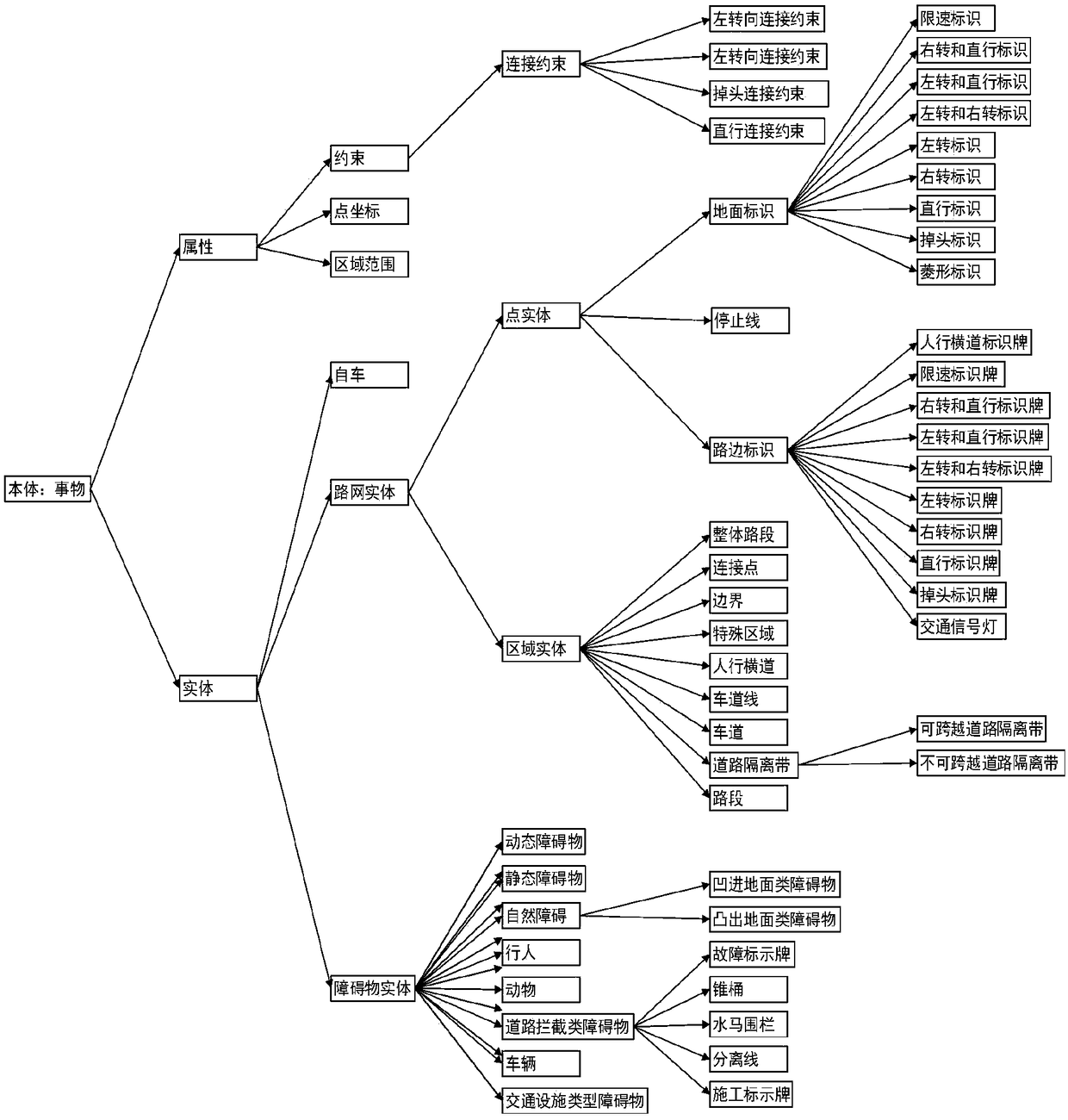
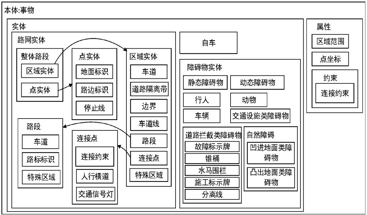
[0042] Such as image 3 As shown, the semantic ontology is divided into two modules: entities and attributes:

[0043] (1) Entities include self-vehicle, road network entity and obstacle entity, respectively representing the self-vehicle (unmanned vehicle) entity, road network element entity and obstacle entity.

[0044] (11) The self-vehicle refers to the unmanned vehicle itself, which can be expanded to different types of unmanned vehicles according to the needs.

[0045] (12) Road network entities include area entities and point entities, representing area type entities and point type entities respectively.

[0046] (121) Regional entities include overall road sections, connection points, boundaries, road separation strip...

specific Embodiment 2

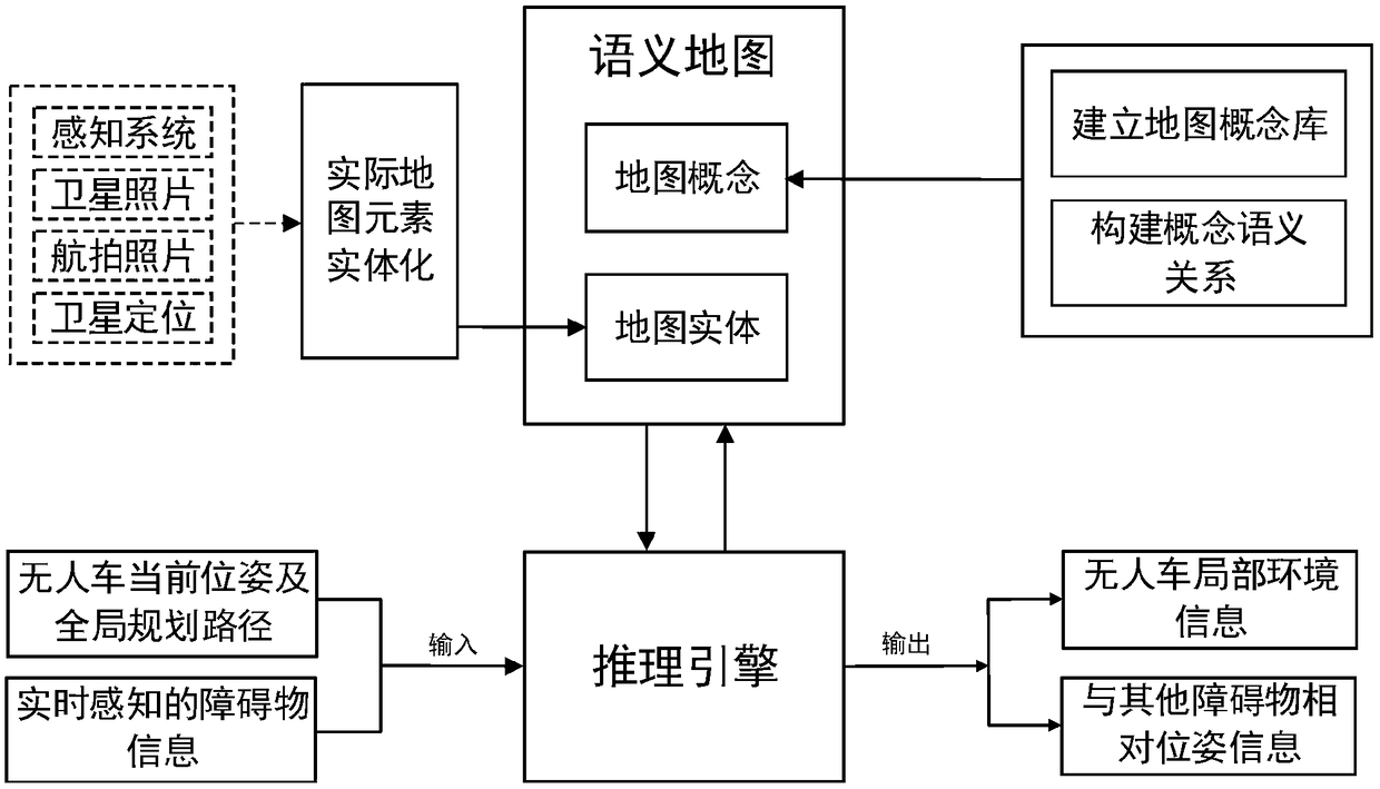
[0060] Such as Image 6 As shown, the method of static map data instantiation and real-time obstacle instantiation to generate a semantic map, the steps are as follows:

[0061] Step 1: Obtain detailed data information of the real driving environment through perception systems such as lidar, camera, GPS, and satellite photos, and instantiate the detailed map data into static road network entities according to the conceptual structure of the map;

[0062] Step 2: Obtain real-time obstacle pose information through sensors such as lidar, camera, and GPS, and instantiate the obstacle information into an obstacle map entity;

[0063] Step 3: Establish the semantic relationship between the entities in the static map obtained in Step 1 and Step 2 and the obstacle map, and finally obtain the semantic map for unmanned vehicles.

specific Embodiment 3

[0064] Such as Figure 7 As shown, it is a modeling example diagram of a real map, which includes a crossroad, a U-turn, multiple road sections and other map elements. The key elements are marked with arrows, and the ground signs and roadside signs are only Take one as an illustration.

[0065] Firstly, the detailed map data is obtained; then, the detailed map data is divided into different types of map elements according to the conceptual structure of the semantic map and instantiated into static road network entities according to the aforementioned conceptual structure.

[0066] As shown in the figure, the horizontal and vertical roads represent two overall road segment entities. The intersection entity is connection point 002, and the U-turn entity is connection point 001. Each road segment is connected to other road segments through connection points. The middle of the road The dotted arrow represents the connection constraint entity, which is associated with the connecti...


PUM


Abstract

The invention discloses an unmanned vehicle semantic map modeling and application constructing method based on perception and location monitoring and relates to the technical field of unmanned driving. According to the method in the invention, two concept modules, namely entity and attribute, are included in unmanned vehicle semantic map modeling, wherein the entity comprises a vehicle entity, a road network entity and an obstacle entity; the road network entity comprises region entity and point entity; the attribute comprises point coordinate, area coverage and constraint; and the semantic relation is divided into two parts, namely object attribute and data attribute. According to the method disclosed by the invention, a set of map element data hierarchy structure applicable to the unmanned vehicle is constructed, and by designing the sufficient semantic relationship among map elements, the semantic map is conveniently generated; and semantic reasoning is performed on the semantic map, global planning path, the current posture of the unmanned vehicle and surrounding real-time obstacle information so as to obtain local scene information of the unmanned vehicle, the unmanned vehicleis assisted in performing behavior decision, understanding of the unmanned vehicle on driving scene elements is efficiently completed, and the associated search efficiency of the map elements is improved.

Description

technical field [0001] The invention relates to the field of unmanned driving technology, in particular to an application method for modeling and constructing semantic maps of unmanned vehicles based on perception positioning monitoring. Background technique [0002] In recent years, unmanned driving has received extensive attention from domestic and foreign academic and industrial circles, and its related supporting technologies have developed rapidly. From the perspective of unmanned driving application products, they can generally be divided into two categories: unmanned driving products for industrial production applications and unmanned driving products for personal consumption applications. In terms of the composition of the unmanned driving technology system, the unmanned driving system can generally be divided into sub-modules such as environmental perception, decision planning, and motion control. Environmental perception is to obtain real-time scene information of ...

Claims


Application Information

Patent Timeline
IPC IPC(8): G01C21/32
CPCG01C21/32
Inventor 项卫锋季彩玲王池如王晓彬
Owner 安徽宇锋智能科技有限公司
Why Eureka
Try Eureka