Electromagnetic coil magnetic drive operation method, magnetic drive mechanism and impact device

A magnetic drive and electromagnetic coil technology, applied in electromagnets, electromagnets with armatures, circuits, etc., can solve problems such as inability to pass through the whole process, limited movement of magnetic induction bodies, and restrictions on the application range and fields of electromagnetic products, and achieve Small wear, direct energy conversion, ingenious effect

Pending Publication Date: 2018-12-11
邵金安
View PDF0 Cites 6 Cited by
  • Summary
  • Abstract
  • Description
  • Claims
  • Application Information

AI Technical Summary

Problems solved by technology

[0002] In the prior art, the products driven by electromagnetic coils for linear operation include relays, contactors, solenoid valves, etc. Due to the principle that the two poles of the magnetic field of the electromagnetic coil have equal energy and opposite directions, that is, the magnetic field of the electromagnetic coil has equal energy and opposite magnetic poles at the two poles. , the magnetic inductor (made of ferromagnetic materials such as iron, cobalt, nickel) generate

Method used


Image

  • Electromagnetic coil magnetic drive operation method, magnetic drive mechanism and impact device
  • Electromagnetic coil magnetic drive operation method, magnetic drive mechanism and impact device
  • Electromagnetic coil magnetic drive operation method, magnetic drive mechanism and impact device

Examples


Embodiment 1

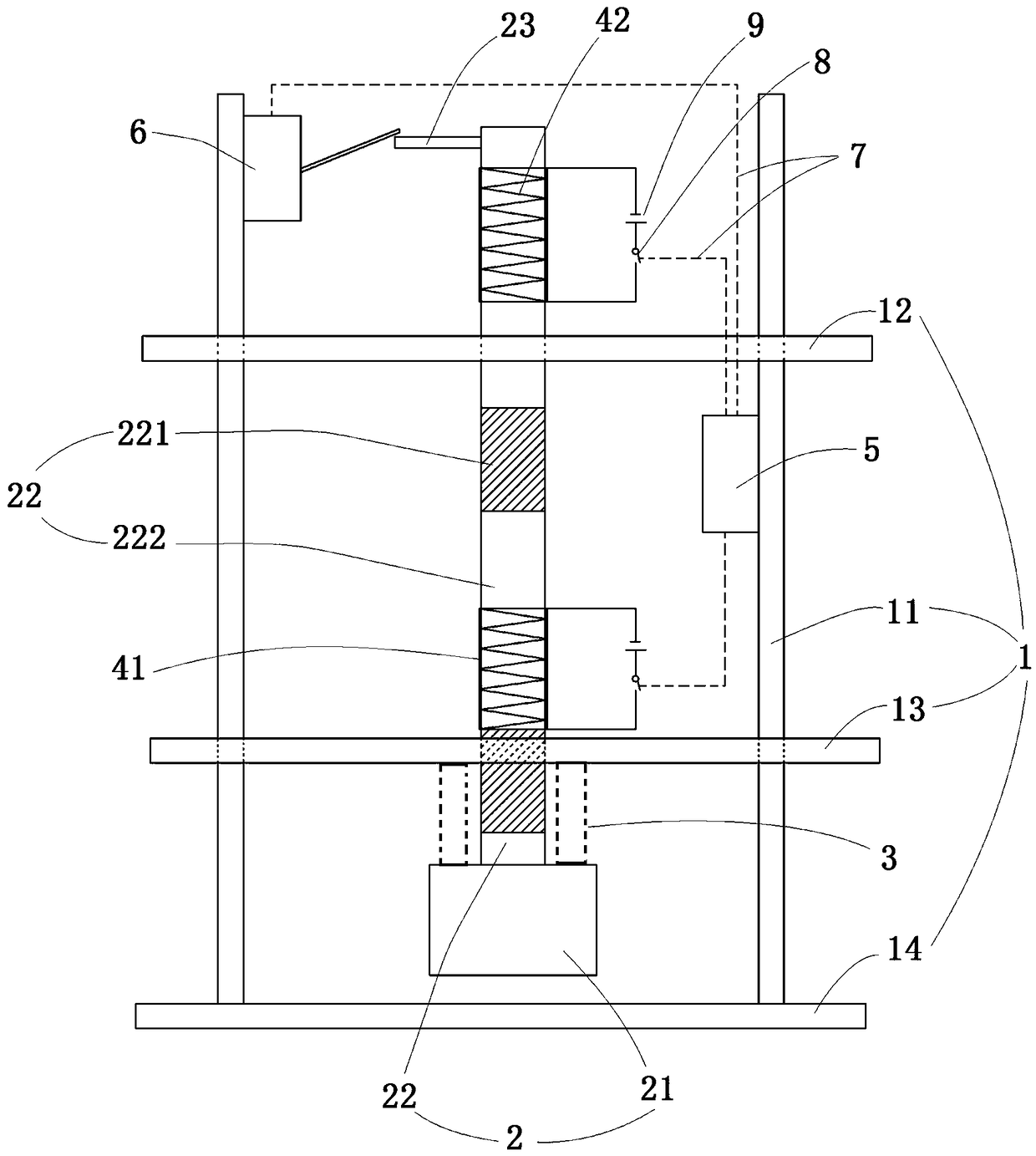
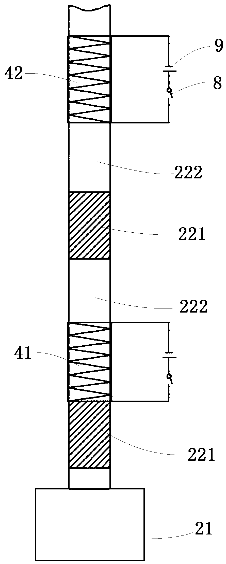
[0041] Embodiment 1 of the electromagnetic coil magnetic driving operation method of the present invention: This embodiment is described for a coil, that is, the number of coils m=1, and the magnetic induction body is a moving body, and the coil is a fixed body. A magnetic induction body is arranged on one side of the axial direction of the coil, and the magnetic induction body is arranged in the magnetic induction area formed by one end of the coil after the coil is energized so that the coil can be attracted after the coil is energized, and then the coil is energized by the controller, and the coil The generated magnetic field attracts the magnetic sensor, so that the magnetic sensor moves along the axis of the coil to the direction close to the coil. When the magnetic sensor moves to the middle position of the magnetic core of the coil magnetic field, the control coil is powered off, and the magnetic sensor The body continues to move forward under the action of inertia, so t...

Embodiment 2

[0042] Embodiment 2 of the electromagnetic coil magnetic driving operation method of the present invention: This embodiment is described for the scheme of more than two coils, that is, the number of coils m≥2, and the magnetic induction body is a moving body, and the coil is a fixed body. Set two or more coils in sequence along the set straight line, the number of coils is selected according to the needs of use, the axis of the coil is collinear with the set straight line, and the magnetic induction body is arranged on the front side of the first coil axis direction and the magnetic induction body Located in the magnetic induction area formed by the front end of the first coil after it is energized, the controller controls the first coil to be energized, and the magnetic induction body moves toward the first coil along the axis of the coil, and then adopts the following control steps: When the magnetic induction When the magnetic core of the body moves to the center of the magn...

Embodiment 3

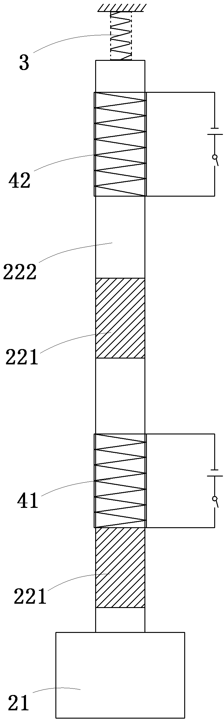
[0043] Embodiment 3 of the electromagnetic coil magnetic driving operation method of the present invention: This embodiment is described for a coil, that is, the number of coils n=1, and the magnetic induction body is a moving body, and the coil is a fixed body. A magnetic induction body is arranged on one side of the coil axis direction, and limit pieces are respectively provided at the front and rear limit positions of the magnetic induction body to limit the range of motion of the magnetic induction body between the two limit pieces; There are also front and rear initial positions in the moving stroke that are respectively located in the magnetic induction area formed by the front and rear ends of the coil when it is energized. The following control steps are adopted: when the magnetic induction body is located at the front initial position, the coil is controlled by the controller. When energized, the magnetic sensor moves toward the coil along the axis of the coil. When th...


PUM


Abstract

The invention relates to a magnetic drive operation method of an electromagnetic coil, a magnetic drive mechanism and an impact device. The drive mechanism comprises a coil and a combination body which moves relative to the coil and is formed by a combination of a magnetic induction section and a non-magnetic induction section, the impact device comprises a frame, The hammer body, coil and the controller that controls the power of the coil, Through the unique control of the coil, A magnetic inductor is driven by a magnetic field generate by that coil when the magnetic inductor is energized when the magnetic inductor is locate in the magnetic induction region at the front end of the coil, the coil is de-energized when the magnetron moves to the position of the reverse magnetic field regionof the coil, so as to realize unipolar and unidirectional driving of the coil to the magnetic inductor, ingeniously conceived, A linear or linear reciprocate motion of a magnetic inductor driven by anelectromagnetic force can produce an impact hammer, Impact rammer, pile driver, crusher, foundation tamper, vibrator, etc., or applied in rail transportation, transportation and military field, can use electromagnetic to do work for long-distance and reciprocating operation, with the advantages of direct energy conversion, pollution-free, small wear and tear, etc.

Description

technical field [0001] The invention relates to a magnetic driving operation method of an electromagnetic coil, a magnetic driving mechanism and an impact device. Background technique [0002] In the prior art, the products driven by electromagnetic coils for linear operation include relays, contactors, solenoid valves, etc. Due to the principle that the two poles of the magnetic field of the electromagnetic coil have equal energy and opposite directions, that is, the magnetic field of the electromagnetic coil has equal energy and opposite magnetic poles at the two poles. , the magnetic inductor (made of ferromagnetic materials such as iron, cobalt, nickel) generates an indirect magnetic field under the induction of the magnetic field and attracts the coil. When the magnetic inductor moves relative to the coil, when the magnetic inductor is close to the coil Being attracted, it will be attracted in the opposite direction when it is away from the coil, so that the magnetic se...

Claims


Application Information

Patent Timeline
IPC IPC(8): H01F7/16
CPCH01F7/1638H01F2007/1692
Inventor 邵金安邵振华刘晓森
Owner 邵金安
Why Eureka
Try Eureka