Novel knee joint prosthesis

A knee joint prosthesis and a new type of technology, applied in the field of medical devices, can solve the problems of easy detachment of the tibial tray and the gasket, and achieve the effect of preventing detachment and easy assembly

Pending Publication Date: 2018-12-14
优适医疗科技(苏州)有限公司
View PDF0 Cites 2 Cited by
  • Summary
  • Abstract
  • Description
  • Claims
  • Application Information

AI Technical Summary

Problems solved by technology

[0004] The present invention proposes a new type of knee joint prosthesis, which solves the problem of easy detachment of the tibial tray and spacer in the prior art

Method used


Image

  • Novel knee joint prosthesis
  • Novel knee joint prosthesis
  • Novel knee joint prosthesis

Examples


Embodiment 1

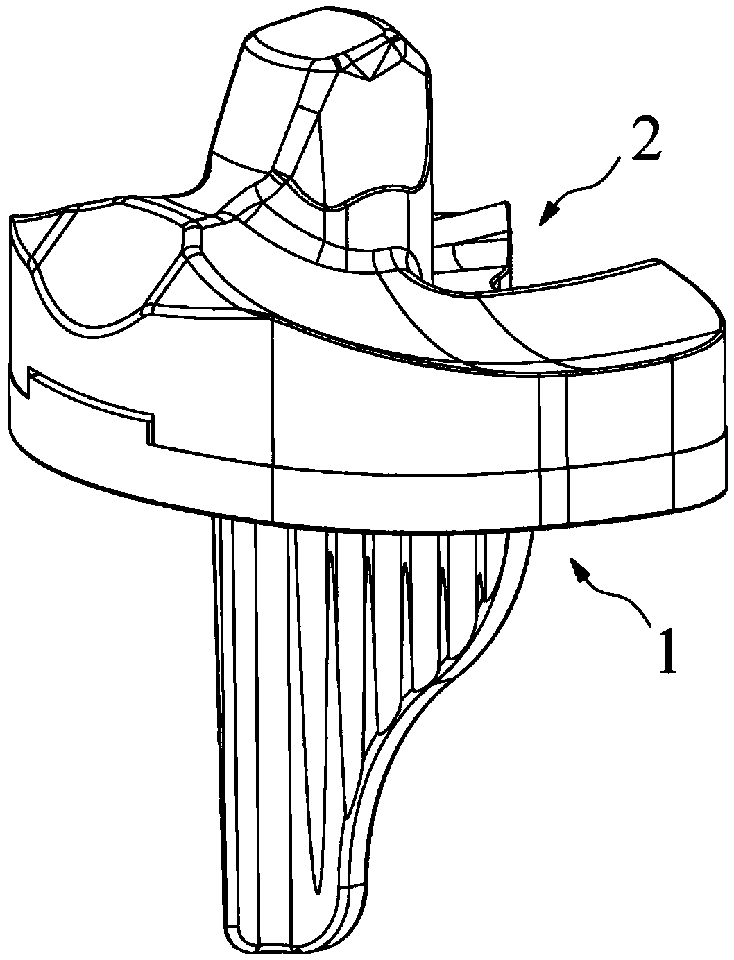
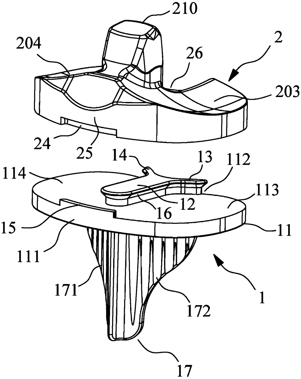
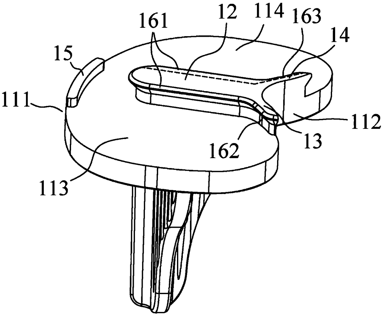
[0035] Such as figure 1 As shown, the new knee prosthesis includes a tibial tray 1 and a spacer 2, and the tibial tray 1 and the spacer 2 are fastened together. Such as Figure 2-5 As shown, the tibial tray 1 comprises a platform 11 comprising an anterior edge 111 and a posterior edge 112 . The platform 11 is provided with a first limiting column 12, a second limiting column 13, a third limiting column 14 and a limiting block 15, the limiting block 15 extends along the front edge 111, and the second limiting column 13 extends along the front edge 111. The rear edge 112 extends, the third limiting column 14 extends away from the rear edge 112, the first limiting column 12 extends away from the second limiting column 13 and the third limiting column 14 toward the front edge 111, along the first limiting column At least two side edges of 12 , the inner edge of the second limiting post 13 and the inner edge of the third limiting post 14 are provided with undercut surfaces 16 . ...

Embodiment 2

[0049] Such as Figure 12-15 As shown, in this embodiment, the first limiting post 12 , the second limiting post 13 and the third limiting post 14 are not connected. The first groove 21, the second groove 22 and the third groove 23 are configured to respectively accommodate the shapes of the first limit post 12, the second limit post 13 and the third limit post 14, so the first groove 21. The second groove 22 and the third groove 23 are also not connected to each other. In addition, the protrusions 1122, 1123 are in the shape of a convex curve, and the extension length of the second limiting post 13 and the third limiting post 14 exceeds the apex of the rear edge 112, that is, Figure 13 The most vertex P and point P' of the protrusions 1122, 1123 in the middle, the advantage is that the second limit post 13 and the third limit post 14 can not only limit the back and forth of the gasket 2, but also the part beyond the most vertex The spacer 2 can be limited left and right, e...


PUM


Abstract

The invention discloses a novel knee joint prosthesis, which comprises a tibial tray and a washer, wherein the tibial tray comprises a platform; a first limiting column, a second limiting column, a third limiting column and a limiting block are arranged on the platform; the limiting block extends along a front edge; a bottom tangent plane is arranged along at least two edges of the first limitingcolumn, the inner edge of the second limiting column and the inner edge of the third limiting column; the lower surface of the washer is provided with a first groove for accommodating the first limiting column, a second groove for accommodating the second limiting column, a third groove for accommodating the third limiting column and a limiting groove for accommodating the limiting block; and a back-off plane is arranged along the inner side wall of the first groove, the inner side wall of the second groove and the inner side wall of the third groove, and the back-off plane abuts against the bottom tangent plane. The tibial tray and the washer are easy to assemble; the convex edge and the back-off plane have a long length, and the force to prevent the washer from falling out is great; andthe convex edge and the back-off plane are not elastically deformed basically, thereby further preventing separation between the tibial tray and the washer.

Description

technical field [0001] The invention relates to the field of medical instruments, in particular to a novel knee joint prosthesis. Background technique [0002] The human knee joint is composed of the femur or tibia, the fibula, and the patella. Between the femur and tibia are discs of cartilage called the medial and lateral menisci, respectively. There is a groove at the anterior and inferior end of the femur that fits the patella. The surface of these joints is covered with cartilage, which can absorb shock and bear pressure. Cartilage, especially the meniscus, is the most vulnerable part of the human body during exercise. Once the joint is damaged, it will cause joint pain and dysfunction. Artificial joint replacement can effectively rebuild joint function and improve the quality of life of patients. [0003] Artificial total knee joint includes femoral component, tibial component, spacer, the main material of femoral component is usually titanium / cobalt chromium / cobalt ...

Claims


Application Information

Patent Timeline
Patent Type & Authority Applications(China)
IPC IPC(8): A61F2/38
CPCA61F2/38A61F2/389A61F2002/2892A61F2002/30731
Inventor 杨一帆黄飞鹏黄建峰吴震宇
Owner 优适医疗科技(苏州)有限公司
Why Eureka
Try Eureka