
Welding technology for improving pipe and end socket connected J-shaped groove welding line quality

A groove welding seam and welding process technology, which is applied in the field of welding technology of J-shaped groove welding seam quality, can solve the problems of large residual stress of the welding seam, no heat treatment, complex structure, etc., so as to control welding deformation and reduce restraint. degree, the effect of preventing thermal cracking

Active Publication Date: 2018-12-14
SHANGHAI ELECTRIC NUCLEAR POWER EQUIP CO LTD
View PDF10 Cites 6 Cited by
  • Summary
  • Abstract
  • Description
  • Claims
  • Application Information

AI Technical Summary

Problems solved by technology

[0002] In nuclear power and chemical equipment, there is a "J"-shaped weld structure in which the pipe and the head penetrate. Welding method, there is a certain angle (45°-90°) between the pipe penetration and the head, the J-shaped weld structure is relatively complicated, and no heat treatment is performed after welding, so the residual stress in the weld is relatively large; for the welded pipe There are also strict requirements on the position and parallelism of the drive line to meet the alignment of the drive line

Method used


Image

  • Welding technology for improving pipe and end socket connected J-shaped groove welding line quality
  • Welding technology for improving pipe and end socket connected J-shaped groove welding line quality
  • Welding technology for improving pipe and end socket connected J-shaped groove welding line quality

Examples


Embodiment 1

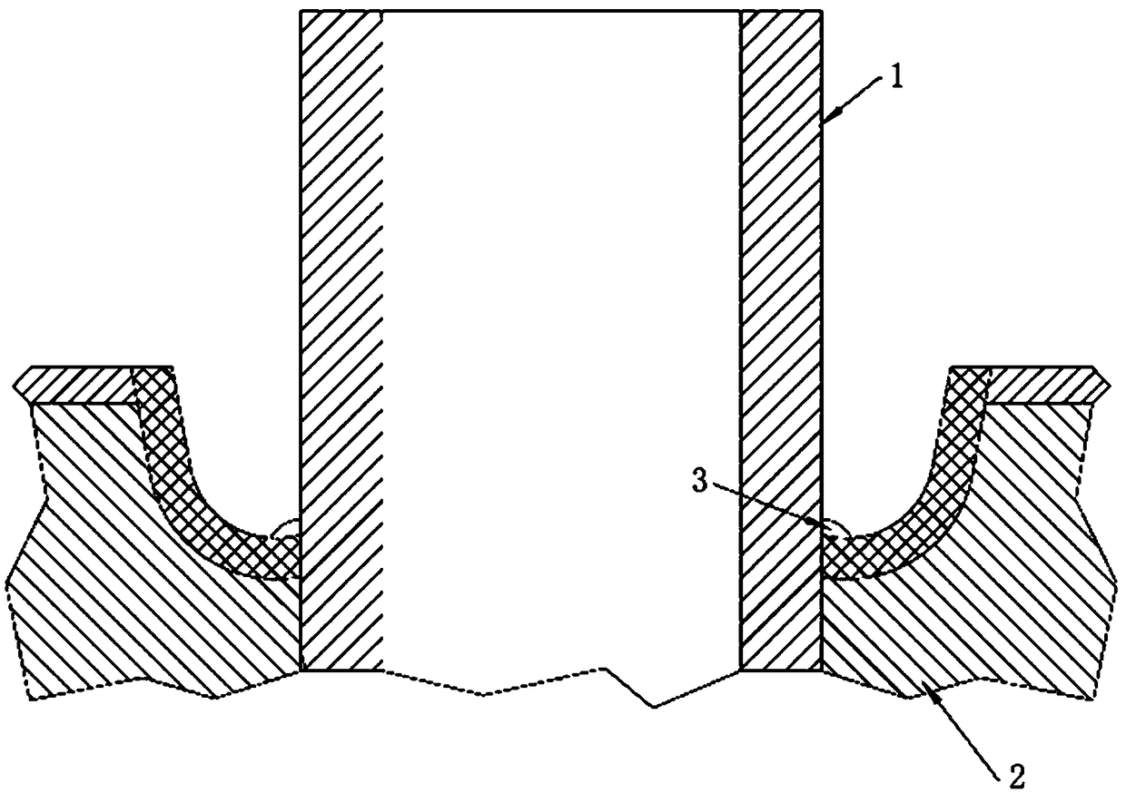
[0038] Example 1: Flat welding position welding of the J-groove weld connecting the pipe 1 and the head 2

[0039] 1. Root pass 3 welding:

[0040] 1) The bottoming weld bead 3 at the root is welded with an electrode with a diameter ≤ Φ2.5mm, close to the pipe wall, and adopts symmetrical welding, such as figure 1 shown;

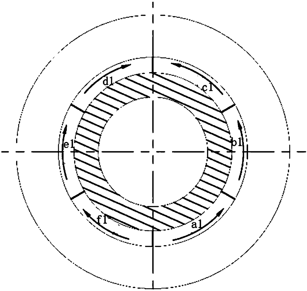
[0041] 2) if figure 2As shown, the root pass 3 is divided into six weld beads of equal arc length a1, b1, c1, d1, e1 and f1 in the counterclockwise direction on the circumference; during welding, a1→f1→b1→e1→c1 → The welding sequence of d1 is carried out, and the welding direction of a1, b1, c1 is counterclockwise, the welding direction of f1, e1, d1 is clockwise, and the welding arc of d1 covers 5 ~ 10mm above c1;

[0042] 3) During the welding process, each weld seam shall be ground after welding, using a pneumatic sand mill for grinding, and the number of sandpaper mesh is ≥ 60 mesh. After welding, it shall be ground for penetration (PT) testing, and ...

Embodiment 2

[0057] Example 2: Double-sided vertical upward welding of the J-groove weld connecting the pipe 1 and the head 2

[0058] 1. Root pass 3 welding:

[0059] 1) Root bottoming weld bead 3 is welded with an electrode with a diameter ≤ Φ2.5mm, close to the pipe wall, welded vertically upwards, and welded from the lowest position, such as Image 6 shown;

[0060] 2) Press Figure 7 As shown, the root pass 3 is divided into six weld beads of equal arc length, a2, b2, c2, d2, e2, f2, in the counterclockwise direction on the circumference; during welding, a2→b2→f2→c2→e2→ The welding sequence of d2 is carried out, and the welding direction of a2, b2, c2 is counterclockwise, the welding direction of f2, e2, d2 is clockwise, and the welding arc of d2 covers 5 ~ 10mm above c2;

[0061] 3) During the welding process, each weld seam shall be ground after welding, using a pneumatic sand mill for grinding, and the number of sandpaper mesh shall be ≥60 mesh; after welding, it shall be ground...


PUM

PropertyMeasurementUnit
Diameteraaaaaaaaaa

Abstract

The invention discloses a welding technology for improving the pipe and end socket connected J-shaped groove welding line quality. As for flat welding or vertical-up welding, the reasonable J-shaped groove welding sequence is adopted for enabling a welding bead to shrink back freely, the restraint intensity is reduced, heat cracks are prevented, meanwhile, the welding bead polishing and flaw detection requirements are provided, welding defects can be effectively reduced, and welding deformation is controlled to a certain degree.

Description

technical field [0001] The invention relates to the field of welding technology, in particular to a welding process for improving the quality of J-groove welds connecting pipes and heads. Background technique [0002] In nuclear power and chemical equipment, there is a "J"-shaped weld structure in which the pipe and the head penetrate. Welding method, there is a certain angle (45°-90°) between the pipe penetration and the head, the J-shaped weld structure is relatively complicated, and no heat treatment is performed after welding, so the residual stress in the weld is relatively large; for the welded pipe There are also strict requirements on the position and parallelism of the drive line to meet the alignment of the drive line. Contents of the invention [0003] The purpose of the present invention is to provide a welding process that improves the quality of the J-groove weld seam connecting the pipe and the head, so that the weld bead shrinks freely, reduces the restrai...

Claims


Application Information

Patent Timeline
IPC IPC(8): B23K33/00B23K31/02B23K9/02B23K9/235B23K101/06
CPCB23K9/02B23K9/235B23K31/027B23K33/004
Inventor 孟令奇钱红妹李双燕张茂龙
Owner SHANGHAI ELECTRIC NUCLEAR POWER EQUIP CO LTD
Learn More