
Sediment sludge dewatering device

A technology for dewatering equipment and sludge, which is used in water/sludge/sewage treatment, sludge treatment, dehydration/drying/concentrated sludge treatment, etc. And other issues

Inactive Publication Date: 2018-12-14
泉州市君健智能家居设备有限公司
View PDF0 Cites 3 Cited by
  • Summary
  • Abstract
  • Description
  • Claims
  • Application Information

AI Technical Summary

Problems solved by technology

[0005] In order to overcome the disadvantages of complicated operation process, low sludge dewatering rate and long time-consuming in the existing sedimentation sludge dewatering equipment, the technical problem to be solved by the present invention is to provide a simple and feasible operation, relatively low dewatering rate High-efficiency, short-time-consuming sedimentation sludge removal equipment

Method used


Image

  • Sediment sludge dewatering device
  • Sediment sludge dewatering device

Examples


Embodiment 1

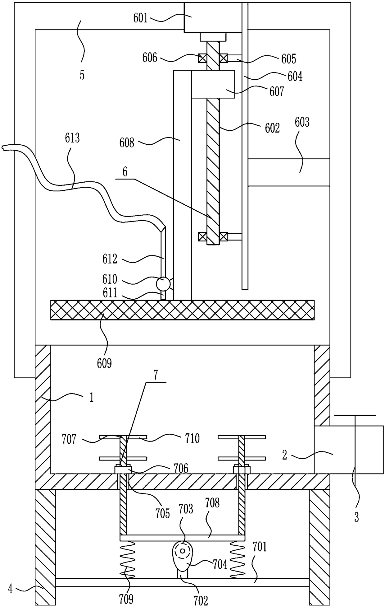
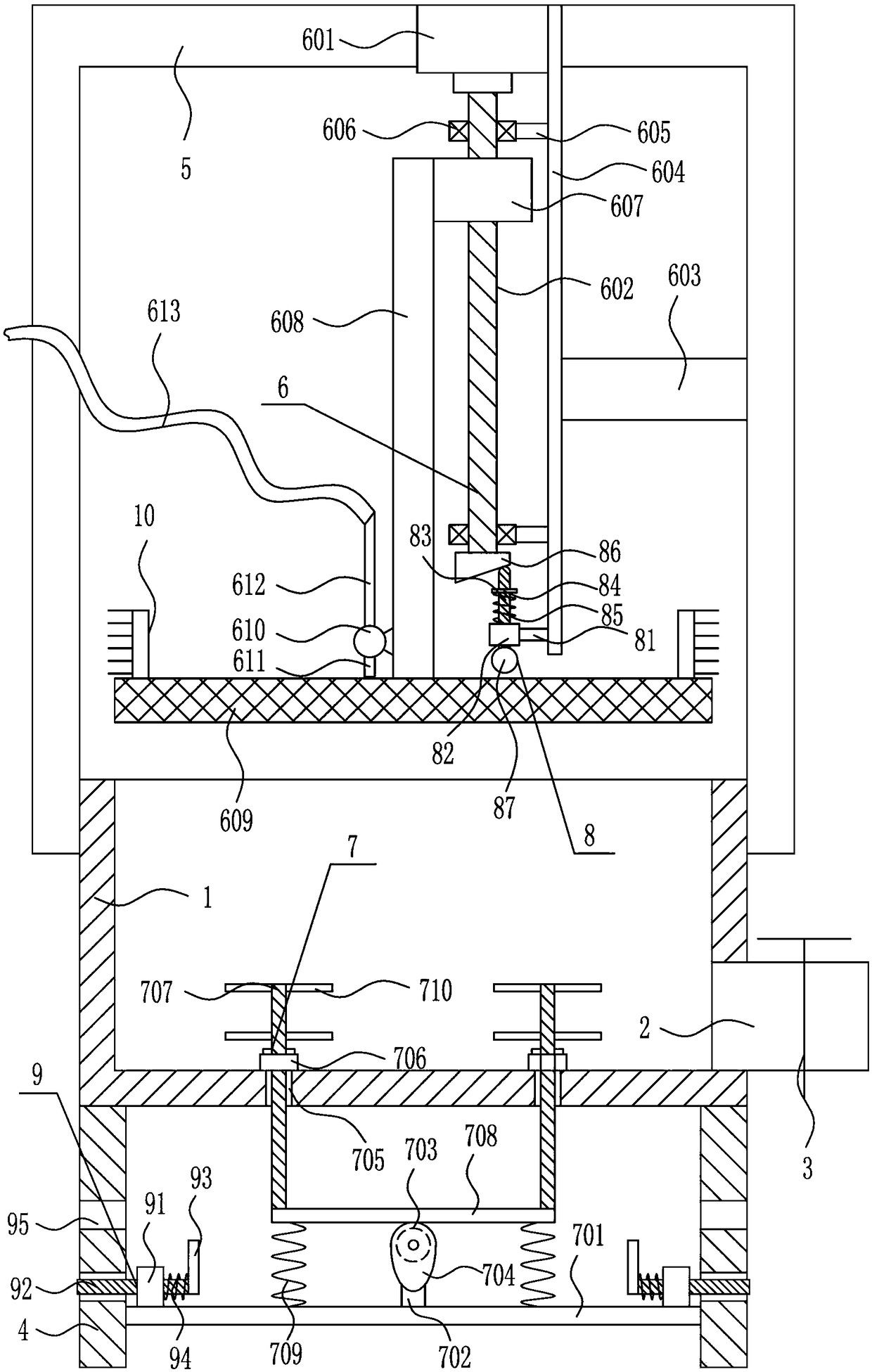
[0026] A sedimentation sludge removal equipment, such as Figure 1-2As shown, it includes a treatment box 1, a feed pipe 2, a valve 3, a leg 4, a protection frame 5, a pressing mechanism 6 and a shaking mechanism 7, and the right side of the treatment box 1 is provided with a feed pipe 2, and the feed pipe 2 is provided with a valve 3, the bottom of the processing box 1 is provided with a leg 4, the top of the processing box 1 is provided with a protective frame 5, and a pressing mechanism 6 is installed inside the protective frame 5, and a shaking mechanism 7 is installed on the processing box 1. .

Embodiment 2

[0028] A sedimentation sludge removal equipment, such as Figure 1-2 As shown, it includes a treatment box 1, a feed pipe 2, a valve 3, a leg 4, a protection frame 5, a pressing mechanism 6 and a shaking mechanism 7, and the right side of the treatment box 1 is provided with a feed pipe 2, and the feed pipe 2 is provided with a valve 3, the bottom of the processing box 1 is provided with a leg 4, the top of the processing box 1 is provided with a protective frame 5, and a pressing mechanism 6 is installed inside the protective frame 5, and a shaking mechanism 7 is installed on the processing box 1. .

[0029] The pressing mechanism 6 includes a first motor 601, a screw mandrel 602, a first pole 603, a first fixed pole 604, a second pole 605, a bearing seat 606, a nut 607, a second fixed pole 608, a mesh plate 609, Water pump 610, first conduit 611, second conduit 612 and water conduit 613, the middle of protection frame 5 top is installed with first motor 601, is connected wi...

Embodiment 3

[0031] A sedimentation sludge removal equipment, such as Figure 1-2 As shown, it includes a treatment box 1, a feed pipe 2, a valve 3, a leg 4, a protection frame 5, a pressing mechanism 6 and a shaking mechanism 7, and the right side of the treatment box 1 is provided with a feed pipe 2, and the feed pipe 2 is provided with a valve 3, the bottom of the processing box 1 is provided with a leg 4, the top of the processing box 1 is provided with a protective frame 5, and a pressing mechanism 6 is installed inside the protective frame 5, and a shaking mechanism 7 is installed on the processing box 1. .

[0032] The pressing mechanism 6 includes a first motor 601, a screw mandrel 602, a first pole 603, a first fixed pole 604, a second pole 605, a bearing seat 606, a nut 607, a second fixed pole 608, a mesh plate 609, Water pump 610, first conduit 611, second conduit 612 and water conduit 613, the middle of protection frame 5 top is installed with first motor 601, is connected wi...


PUM


Abstract

The invention relates to a processing device, and in particular relates to a sediment sludge dewatering device. The technical problem to be solved by the invention is to provide a sediment sludge dewatering device with simple and feasible operation, high dewatering rate and low time cost. In order to solve the technical problem, the invention provides the sediment sludge dewatering device. The device comprises a treatment box; the right side of the treatment box is provided with a material guide pipe; the material guide pipe is provided with a material guide valve; supporting legs are arrangedat the bottom of the treatment box; a protection frame is arranged at the top of the treatment box; a pressing mechanism is installed in the protection frame; and a shaking mechanism is installed onthe treatment box. According to the device, through mutual match of the pressing mechanism and the shaking mechanism, sludge added into the treatment box is subjected to dewatering treatment, and meanwhile, optimization is carried out by using an auxiliary mechanism and a height adjusting mechanism, so that effects of simple and feasible operation, high dewatering rate and low time cost are achieved.

Description

technical field [0001] The invention relates to a processing device, in particular to a sedimentation sludge dewatering device. Background technique [0002] Sewage treatment is the process of purifying sewage to meet the water quality requirements of a certain water body for drainage or reuse. Sewage treatment is widely used in various fields such as construction, agriculture, transportation, energy, petrochemical, environmental protection, urban landscape, medical treatment, catering, etc., and it is also increasingly entering the daily life of ordinary people. [0003] The sludge needs to be dewatered during the sedimentation process, so as to ensure that the sludge can quickly reach the operator's expected purpose. The existing sedimentation sludge dewatering equipment has complex operation process, low sludge dewatering rate, and takes a long time. Therefore, there is an urgent need to develop a sedimentation sludge removal equipment that is easy and feasible to operat...

Claims


Application Information

Patent Timeline
Patent Type & Authority Applications(China)
IPC IPC(8): C02F11/12
CPCC02F11/121
Inventor 丁中明
Owner 泉州市君健智能家居设备有限公司
Learn More