Method and device for controlling flow of zinc liquid in hot-dip galvanizing pot

一种流动控制、热镀锌的技术,应用在对表面涂布液体的装置、热浸镀工艺、涂层等方向,达到防止锌资源消耗、减少人工操作、避免堆积结块的效果

Active Publication Date: 2020-04-28
BAOSHAN IRON & STEEL CO LTD
View PDF9 Cites 2 Cited by
  • Summary
  • Abstract
  • Description
  • Claims
  • Application Information

AI Technical Summary

Problems solved by technology

However, this patent is mainly aimed at circular molten iron ladles. The arrangement of the traveling wave magnetic field and the control of the direction of the magnetic field are relatively simple, and it must cooperate with the slag tank to work normally. Consider the impact of molten iron flow on product quality

Method used


Image

  • Method and device for controlling flow of zinc liquid in hot-dip galvanizing pot
  • Method and device for controlling flow of zinc liquid in hot-dip galvanizing pot
  • Method and device for controlling flow of zinc liquid in hot-dip galvanizing pot

Examples


Embodiment 1

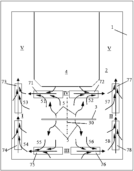
[0038] see figure 2 A total of 8 sections of traveling wave magnetic field generators are installed on the left and right sides of the zinc pot 1 hot-dip area (area I and area II), the front end (area III) and the position between the strip steel 3 and the furnace nose 4 (area IV). Respectively: the first left segment traveling wave magnetic field generator 73, the second left segment traveling wave magnetic field generator 74, the first right segment traveling wave magnetic field generator 77, the second right segment traveling wave magnetic field generator 78, the first front segment traveling wave magnetic field generator 75, the first Two rear traveling wave magnetic field generators 76 , a first rear traveling wave magnetic field generator 71 , and a second rear traveling wave magnetic field generator 72 .

[0039] The first left segment traveling wave magnetic field generator 73, the second left segment traveling wave magnetic field generator 74, the first front segment...

Embodiment 2

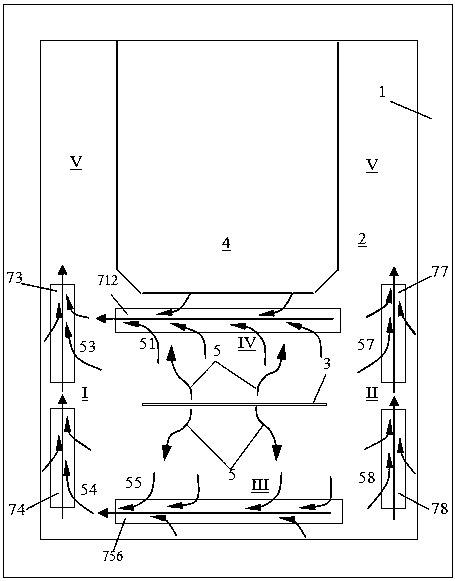
[0047] see image 3 , the transversely arranged traveling wave magnetic field generator located at the front end of the zinc pot (Zone III) and the position between the strip steel and the furnace nose (Zone IV) is a full-length type, that is, the front traveling wave magnetic field generator 756 and the rear traveling wave magnetic field generator 756 Magnetic field generator 712, and the direction of the traveling wave magnetic field excited by the whole length type traveling wave magnetic field generator is in the same direction, so as to drive the zinc liquid to flow to a certain side of the zinc pot, and generate The liquid zinc flow is connected, and the liquid zinc driven by the transverse traveling wave magnetic field generator is turned and driven to the rear end of the zinc pot (V zone).

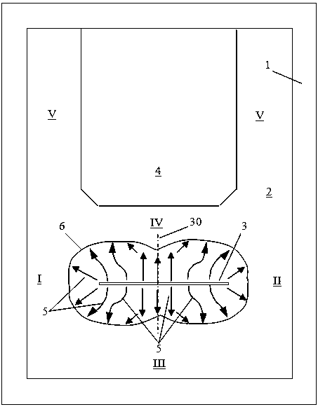
[0048] Depend on figure 1 It can be seen that in the prior art, under the blowing action of the air knife, the liquid zinc flows obliquely along the center line of the strip to bo...


PUM


Abstract

The invention discloses a method and a device for controlling the flow of zinc liquid in a hot-dip galvanizing pot. The control method of the present invention is: the blowing effect of the air knife above the hot-dip galvanizing zinc pot (1) on the strip steel (3) promotes the zinc liquid (2) to the left side, the right side, the front end of the zinc pot, and the strip steel The area (I, II, III, and IV) formed between the furnace nose (4) diffuses and flows outwards, and drags the rapidly generated surface slag on the surface of the zinc liquid to flow outwards to the area; in the area On the edge side, multi-stage traveling wave magnetic field generators (71, 72, 73, 74, 75, 76, 77, 78) are set above the surface of the zinc liquid in the zinc pot to excite the traveling wave magnetic field to generate electromagnetic driving force for the liquid zinc to drive the liquid zinc to flow , the zinc liquid flow caused by the traveling wave magnetic field generator is connected with the spray flow of the air knife to promote the orderly flow of the zinc liquid on the surface layer of the zinc pot to the rear end of the zinc pot (the V zone); the surface floating on the surface of the zinc liquid The slag is dragged by the flowing zinc liquid to flow in a controlled direction.

Description

technical field [0001] The invention relates to the technical field of hot-dip galvanizing, in particular to a method and device for controlling the flow of zinc liquid in a hot-dip galvanizing pot. Background technique [0002] As we all know, the hot-dip galvanizing process is completed by the strip steel passing through the zinc pot. Among them, the strip steel entering the zinc pot at high speed, the movement of the sinking roller assembly in the zinc pot, and the blowing action of the air knife will inevitably cause the flow of zinc liquid. At the same time, the zinc liquid and aluminum components in the zinc pot are particularly active at high temperatures (about 450°C, and the temperature of the aluminum plating pot is as high as 650°C), and have complex chemical reactions with the Fe elements brought in by the strip steel to form Zn -Fe-Al ternary metal compounds, etc., namely zinc slag, zinc slag can be divided into surface slag (also known as scum), suspended slag ...

Claims


Application Information

Patent Timeline
Patent Type & Authority Patents(China)
IPC IPC(8): C23C2/06
CPCC23C2/06C23C2/00C23C2/0034C23C2/40C23C2/325C23C2/50C23C2/0035B05C3/02
Inventor 侯晓光钱洪卫于雷李山青陆勇金鑫焱周月明
Owner BAOSHAN IRON & STEEL CO LTD
Why Eureka
Try Eureka